
Core Powder Fluidization Mechanics and Gravity Conveying Principles
An air slide conveyor transforms cohesive bulk dry powders into a near-frictionless pseudo-fluid state. By balancing microscopic air-particle aeration, differential pressure gradients across a permeable membrane, and gravitational incline vectors, powder travels efficiently without mechanical drive components.
Static Packed Bed Condition
Static StateWithout aeration, bulk dry powder rests compacted directly on top of the air slide fabric. Particle-to-particle interlocking generates substantial internal shear resistance and an elevated angle of repose, preventing gravitational discharge.
- ▪ Particle Interlocking: Void fractions remain compressed at minimum levels with maximum bulk density.
- ▪ Internal Friction Barrier: Static cohesion halts all material movement regardless of standard chute slope.
Gas-Solid Two-Phase Flow Equilibrium & Velocity Control
Stable air gravity conveying requires maintaining superficial air velocity strictly between the minimum fluidization velocity (Umf) and the terminal elutriation velocity (Ut). When airflow velocity operates within this threshold, upward aerodynamic drag matches the buoyant gravitational weight of the powder bed, eliminating internal shear without carrying particles into turbulent suspension.
Operating below Umf causes localized defluidization and chute blockage, whereas exceeding Ut creates severe bubbling, dust elutriation, and accelerated wear on upper housing panels. DARKO Cement Machinery engineers air slide fluidization systems with precision-calibrated fabric permeability and plenum pressure zoning, guaranteeing a stable dense-phase pseudo-liquid stream while integrating auxiliary dust-collection equipment to safely manage venting exhaust. Depending on installation requirements, continuous particulate control can be supported by high-efficiency baghouse dust collectors or dedicated pulse-jet dust collectors at critical chute transfer points.
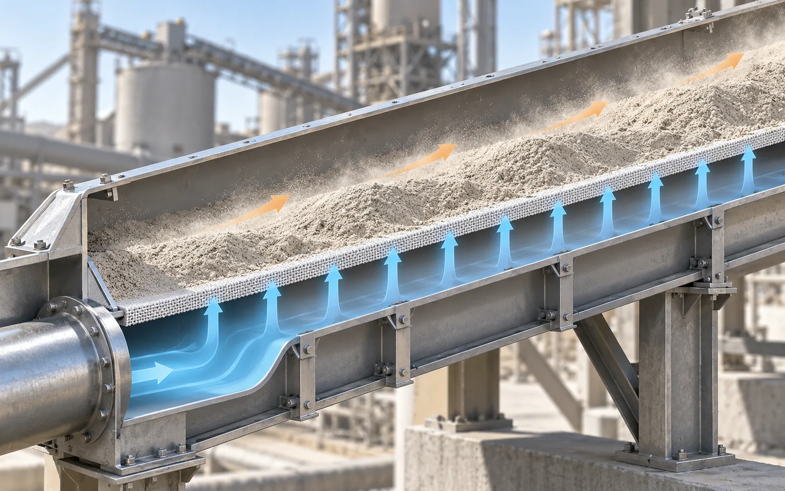
Fluidization Phase Transition
Cross-sectional schema illustrating low-pressure airflow lifting fine dry powder over an inclined microporous air slide fabric layer.
Key Fluidization Design Thresholds
Engineered bulk density calculations ensure reliable flow properties across Portland cement, raw meal, pulverized fly ash, hydrated lime, and blast furnace slag.
1. Ergun Equation Pressure Drop
Determines aerodynamic resistance across the packed powder bed prior to incipient fluidization, accounting for sphericity, voidage, and air viscosity.
2. Minimum Fluidization Velocity (Umf)
Defines the critical superficial gas velocity where upward drag forces counterbalance apparent particle weight, initiating the pseudo-liquid phase.
3. Gravity Flow Component (Fg)
Calculates driving force as a function of aerated mass and the sine of the chute slope (m·g·sin θ), ensuring stable and predictable volumetric flow.
Air Slide Conveyor Parts and Key Structural Components
The industrial air slide conveyor operates using an enclosed bipartite trough structure separated horizontally by a porous fluidizing partition. This split-channel architecture transforms dry bulk powders into fluid-like suspensions that glide downward along a slight downward incline with zero internal rotating drive shafts. Understanding the mechanical interaction between the upper material transport channel, the permeable fabric membrane, the pressurized air plenum chamber, and downstream flow regulation valves is critical for optimizing plant throughput, minimizing downtime, and ensuring dust-free bulk solids handling.
DARKO Cement Machinery engineers heavy-duty air slide conveyor parts with precision-matched fabrication tolerances, ensuring uniform static aeration across the entire conveying run. By pairing high-density multi-ply aeration fabrics with reinforced structural steel housings, our systems eliminate material dead zones, prevent air bypassing along the perimeter flanges, and endure the severe abrasive wear typical of raw meal, finished cement, fly ash, and ground granulated blast-furnace slag installations.
Upper and Lower Chute Design Synergy in Air Gravity Conveying
Industrial air gravity conveyors depend on continuous geometric alignment. The structural steel casing comprises two matching formed channels securely bolted together along continuous external longitudinal flanges. Clamped between these structural lips sits the air slide fabric membrane, supported by heat-resistant perimeter gaskets that deliver both atmospheric dust isolation in the upper channel and airtight pressurization within the lower plenum.
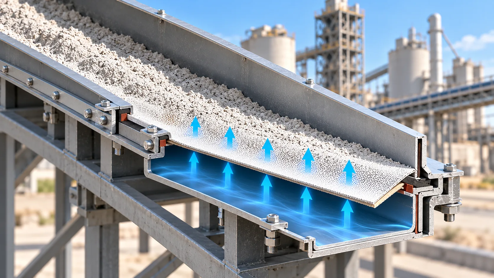
Four Critical Structural Modules of an Air Slide System
Every mechanical module serves a distinct physical role in sustaining powder fluidization dynamics, balancing static pressure gradients, and preventing particulate emissions into the plant environment.
Upper Material Chute
Constructed from heavy-gauge 4 mm to 6 mm structural steel or optional 304/316 stainless steel. Houses fluidized bulk powder within a rigid, dust-tight conveying corridor.
- Dust Vent Ports: Flanged exhaust taps connect directly to plant dust collection equipment and terminal baghouse ducts.
- Inspection Ports: Removable acrylic or tempered glass sight ports for operational monitoring.
- Internal Liners: Optional wear-resistant basalt or Hardox liners at loading impact zones.
Air Slide Fabric Membrane
Multi-ply woven synthetic permeable membrane acting as the fluidization floor. Engineered to maintain consistent airflow resistance while supporting dense material heads.
- Calibrated Permeability: Balanced air resistance across surface (2.0–3.5 m³/m²·min at 1 kPa).
- Engineered Fibers: 100% spun polyester yarn; aramid fibers for temperatures up to 250°C.
- Tensile Rating: Warp tensile resistance exceeds 5,000 N/5cm to prevent sagging under load.
Lower Air Plenum Chamber
Rigid formed U-channel or square chamber withstanding positive blower pressure. Functions as a steady air distribution reservoir beneath the permeable textile membrane.
- Pressure Integrity: Pressure-tested to withstand continuous 6,000 Pa static head without warping.
- Balancing Dampers: Flanged inlet connections fit with manual or pneumatic butterfly valves.
- Purge Ports: Bottom-mounted condensate cleanout drain plugs at low elevation nodes.
Auxiliary Piping & Controls
Integrated flow routing, stream switching, and environmental containment components enabling precise process integration across plant siloing and packing loops.
- Slide Gate Cutoffs: Rapid-closure pneumatic knife gates isolate material streams instantaneously.
- Diverter Valves: Symmetrical two-way and three-way diverter boxes direct flows to multiple bins.
- Blower Silencers: Intake noise reduction filters attenuate acoustic emissions below 75 dBA.
Technical Specifications of Core Structural Components
Standardized mechanical fabrication criteria applied across DARKO air gravity conveyor systems for dry bulk processing.
| Component Assembly | Standard Fabrication Material | Key Engineering Parameter | Primary Operational Function |
|---|---|---|---|
| Upper Conveying Chute | ASTM A36 Carbon Steel / AISI 304/316 SS (4.0–6.0 mm) | Width: 150 mm to 1,000 mm | Encloses powder flow, directs off-gas to dust collector vents |
| Air Slide Fabric Membrane | Multi-ply Woven Polyester / Aramid (Nomex) | Thickness: 4.5–6.0 mm | ΔP: 1.0–1.5 kPa | Creates micro-aeration layer; prevents powder intrusion into plenum |
| Lower Air Plenum Chamber | Cold-Formed Structural Steel (3.0–4.5 mm) | Static Head: 3,000 to 5,000 Pa | Maintains uniform static air cushion beneath permeable canvas |
| Flange Joint Interface | Laser-Cut Angle Flange / Continuous Seal Weld | Bolt Pitch: 75–100 mm (Grade 8.8) | Clamps fabric with uniform perimeter torque to eliminate air bypass |
| Sealing Gasket Media | Expanded EPDM / High-Temp Ceramic Felt | Temp Limit: 120°C (EPDM) / 450°C (Ceramic) | Ensures zero particulate leakage and eliminates pressure dissipation |
| Air Control Butterfly Valve | Ductile Iron Body with Stainless Steel Disc | Inlet Diameters: DN50 to DN250 | Regulates air intake volume to balance fluidization along long runs |
Reliable Spares and Modular Chute Assemblies by DARKO
Whether engineering an entire kiln feeding line or executing rapid air slide fabric replacement during scheduled maintenance shutdowns, DARKO Cement Machinery supplies factory-calibrated components designed to match global plant standards. Our proprietary multi-ply permeable fabrics are woven with tight thread density and pre-stretched to prevent operational elongation, ensuring zero sagging across multi-year continuous production cycles.
All modular housings feature standard bolt-hole patterns compatible with major international OEM dimensions, allowing drop-in upgrades that drastically minimize engineering lead times and plant retrofitting labor.
Air Slide Conveyor Operating Parameters and Engineering Design Baselines
Reliable pneumatic gravity conveying depends on a precise balance between gravitational slope, material aeration dynamics, and plenum static pressure. DARKO Cement Machinery leverages empirical field data across thousands of bulk conveying equipment installations to establish validated design parameters, ensuring consistent fluidization without material segregation or chute choking.
Air Slide Inclination Angle
The standard operating slope ranges from 4° to 8° downward incline, transforming incipient fluidization into continuous, low-friction gravity flow along the chute profile.
- Finished Portland Cement 5° to 6° Slope
- Dry Power Plant Fly Ash 6° to 8° Slope
- Raw Meal & Aeratable Minerals 4° to 5° Slope
Fluidizing Air Pressure and Velocity
Lower air plenum static pressure is engineered to overcome both the fabric permeability barrier and the powder bed head without generating boiling turbulence or fine dust carryover.
- Plenum Blower Static Pressure 3,000 to 5,000 Pa (30–50 mbar)
- Permeable Surface Velocity 1.5 to 3.0 m³/(m²·min)
- Air Velocity Threshold Calibrated per Umf Curve
Allowable Moisture and Particle Sizing
Stable pseudo-liquid behavior requires strict physical moisture boundaries to prevent capillary bridging, agglomeration, and premature fabric blinding.
- Total Free Moisture Content ≤ 1.0% (Ideal < 0.5%)
- Maximum Particle Size Cutoff 100% Passing 1.0 mm
- Fine Fraction Distribution 50% Passing 200 Mesh (75 μm)
Filling Factor and Bed Flow Velocity
Maintaining adequate upper chamber freeboard provides sufficient clearance for de-aeration without choking exhaust venting channels connected to plant baghouse dust collectors.
- Standard Cross-Section Fill Ratio (φ) 0.40 to 0.50 Area Fraction
- Fluidized Bed Travel Velocity 1.2 to 2.5 m/s Nominal
- Upper Venting Freeboard Reserve ≥ 50% Housing Height
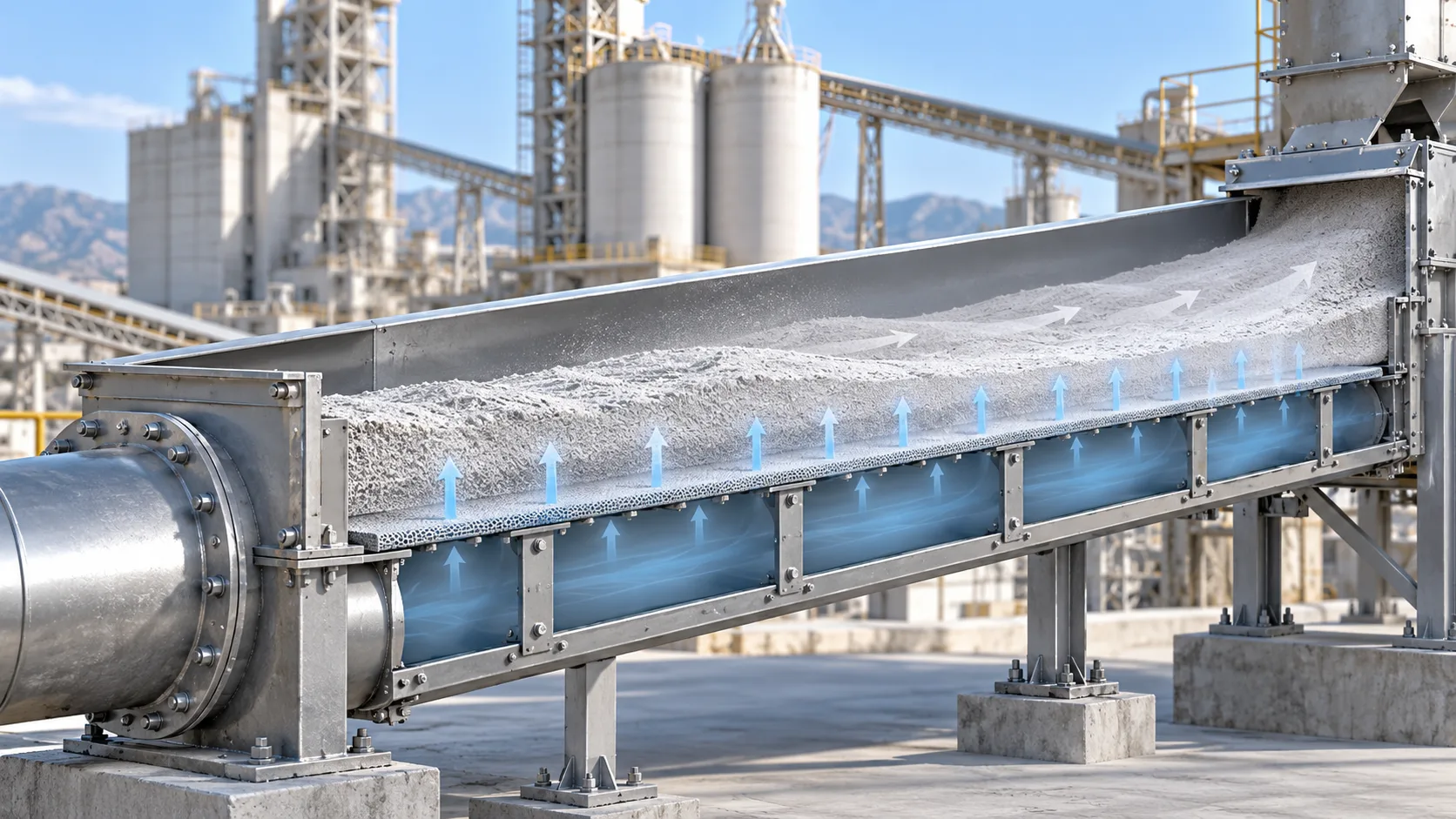
Theoretical Sizing and Capacity Verification Formula
Engineering calculations balance the active trough cross-sectional area with the aerated bulk density of the fluidized powder. Mass throughput calculations follow the continuity relationship developed for aerated gravity conveyors:
Air Flow Delivery and Blower Sizing Principles
Centrifugal blower volumetric delivery is calculated directly from the total permeable surface area of the aeration membrane. Optimal fluidization relies on stable, uniform air diffusion across the complete chute run rather than excessive air volume:
Where L is effective conveyor length (m), W is internal trough width (m), q_specific is the specific air consumption factor (1.5 to 3.0 m³/m²·min), and K_leakage represents a system engineering safety coefficient (1.10 to 1.15) covering exhaust venting balancing.
Material-Specific Engineering Reference Matrix
| Material Grade | Angle of Repose | Recommended Incline | Superficial Air Demand |
|---|---|---|---|
| Finished Portland Cement (OPC) | 35° to 40° | 5.0° to 6.0° | 2.0 m³/(m²·min) |
| Kiln Feed Raw Meal | 30° to 35° | 4.0° to 5.0° | 1.8 m³/(m²·min) |
| Pulverized Fuel Ash (Dry Fly Ash) | 40° to 45° | 6.0° to 8.0° | 2.4 m³/(m²·min) |
| Ground Granulated Slag (GGBFS) | 38° to 42° | 6.0° to 7.0° | 2.2 m³/(m²·min) |
Application Verification Protocol
DARKO Cement Machinery conducts laboratory aerated bulk density testing and membrane permeability verifications to calibrate precise blower head sizing before line commissioning. Contact our process engineering team to request customized design verification sheets, layout slope checks, and specialized air slide conveyors capacity calculations tailored to your bulk powder conveying project.
Technical Comparison: Air Slide vs Screw, Pneumatic, and Mechanical Conveying
Evaluating the air slide conveyor working principle alongside traditional mechanical and pressurized transport methods highlights massive efficiency and reliability gains for dry bulk powders. By replacing continuous mechanical friction with low-pressure fluidization and gravity assist, industrial plants achieve dependable throughput at a fraction of standard power requirements. DARKO Cement Machinery engineers advanced air gravity conveying systems that eliminate moving wear parts and deliver consistent operational cost savings across cement, lime, and fly ash circuits.
| Comparison Metrics | Air Slide Conveyor (Fluidized Gravity) | Screw Conveyor (Mechanical Auger) | Dense Phase Pneumatic (High Pressure) | Bucket Elevator & Belt Systems |
|---|---|---|---|---|
| Specific Energy Consumption | 0.15 – 0.25 kWh/t Ultra-low fan power requirement | 1.50 – 2.50 kWh/t 5x to 10x higher energy demand | 2.00 – 4.50 kWh/t Requires high-pressure compressors | 0.80 – 1.60 kWh/t Driven by heavy drive motors |
| Moving Internal Wear Parts | Zero Moving Parts Static enclosure and permeable fabric | High Contact Wear Continuous flight, shaft, and hanger abrasion | Valve & Elbow Erosion High-velocity particulate scouring | Moderate to High Chains, belts, sprockets, and pulleys |
| Operating Pressure Differential | < 5 kPa (0.05 bar) Low-pressure centrifugal air blower | Atmospheric (0 kPa) Mechanical displacement only | 200 – 600 kPa (2 – 6 bar) High pressure pressure vessels | Atmospheric (0 kPa) Mechanical vertical lift |
| Dust Containment & Enclosure | Fully Hermetic Seal Micro-negative draft integration | Frequent Shaft Leaks Gland packing deterioration over time | Fully Enclosed Piping High containment until pipe wall blowout | Moderate Dust Escape Chute transfer points require venting |
| Conveying Layout Flexibility | 4° to 8° Downward Slope Gravity assistance strictly required | Horizontal to 30° Incline Flexible routing with reduced capacity | Complete 3D Routing Horizontal, vertical, and bends | Vertical 90° Direct Lift Strictly dedicated to vertical elevation |
| 10-Year Lifecycle Cost (TCO) | Lowest Overall TCO Minimal power draw and rare overhauls | High Operating Cost Frequent screw and bearing replacements | High Power & Pipe Cost Continuous high electricity expenses | Moderate Maintenance Periodic chain and belt replacement |
Air Slide vs Screw Conveyor
Screw conveyors rely on brute mechanical force to push abrasive powders along steel troughs, creating heavy friction that thins helical flights, wears hanger bearings, and causes shaft fatigue. Air slides eliminate mechanical drag entirely by floating aerated material down a shallow incline.
- ✓ 80%–90% Lower Power: Operates efficiently with low-pressure aeration fans instead of high-torque motors.
- ✓ Zero Rotating Wear: Eliminates broken screw shafts, seized internal hanger bearings, and trough scouring.
- ✓ Quiet, Smooth Operation: Silent, gravity-induced fluid glide without mechanical noise or vibration.
Air Slide vs Dense Phase Pneumatic
Dense phase pneumatic conveying uses compressed air exceeding 200–600 kPa to force dense material plugs through pipelines. While suited for complex vertical and multi-turn layouts, high transport velocities cause severe elbow erosion, high energy draw, and frequent valve overhauls.
- ✓ Low Pressure Under 5 kPa: Replaces capital-intensive screw compressors with small centrifugal blowers.
- ✓ Negligible Pipe Wear: Gentle laminar fluidized powder flow prevents line blowouts and abrasive puncture.
- ✓ Streamlined System Controls: Eliminates pressure vessels, cycling dome valves, and complex air controls.
Air Slide vs Belt & Bucket Elevators
Belt conveyors and bucket elevators are essential for steep and vertical elevation, but horizontal belts present serious airborne dust containment challenges that require auxiliary dust collection equipment, while bucket elevators require ongoing chain tensioning, bucket realignment, and drive maintenance.
- ✓ 100% Sealed Dust Control: Fully enclosed channel design prevents airborne particulate emissions and minimizes the continuous load on local pulse-jet dust collectors.
- ✓ Integrated Plant Flow: Smoothly feeds vertical bucket elevator inlets with steady, non-surging material flow.
- ✓ Compact Overhead Profile: Low-headroom housing integrates cleanly underneath silos, hoppers, and mills.
Maximizing Process Uptime in Continuous Bulk Powder Handling
Whenever a plant layout accommodates a 4° to 8° gravity decline, air slide conveying offers unmatched operational economy and reliability. By exchanging high-wear mechanical moving components for an aerated micro-fluidization bed, processing plants eliminate surprise breakdowns and slash total plant electrical loads.
Across cement mill discharge circuits, raw meal blending silos, and clinker storage feed lines, DARKO Cement Machinery replaces aging screw conveyors and high-wear piping with custom-engineered air gravity systems seamlessly integrated with plant baghouse dust collectors, consistently cutting line maintenance overhead and unplanned downtime by over 70%.

Air Slide Conveyor Material Suitability and Operational Boundaries
Air gravity conveying relies on converting fine dry powders into a pseudo-fluidized state via uniform, low-pressure aeration. However, this fluid-like gravity flow depends entirely on strict physical, aerodynamic, and chemical thresholds. Establishing precise material boundaries prevents localized packing, fabric pore blinding, and unstable flow velocities across cement plants, power generation facilities, and mineral processing lines equipped with integrated dust collection equipment.
Recommended Powders & Criteria
Proven ApplicationsOptimal materials exhibit high gas-retention properties, minimal surface cohesion, and fine particle size distributions. These powders expand uniformly under gentle micro-aeration, floating freely across the inclined permeable membrane without channeling or premature de-aeration.
Compatible Industrial Bulk Materials
Required Fluidization Properties
- ✓ Particle Fineness: 100% passing a 1.0 mm sieve with at least 50% passing 200 mesh (74 microns) to ensure gas film formation.
- ✓ Free Moisture Limit: Free surface moisture must stay below 1.0% by weight (ideally <0.5%) to prevent fabric binding and caking.
- ✓ Operating Temperature: Standard polyester membranes handle up to 150°C (302°F); specialized aramid fabric supports up to 250°C (482°F).
Incompatible Materials & Limits
Operational ExclusionsFeeding non-fluidizable, wet, or coarse bulk solids into an air slide causes rapid chute clogging, pore blinding, or localized material accumulation. Furthermore, gravitational slide dynamics impose strict limits on conveyor routing.
Prohibited Material Profiles
Geometric & Routing Constraints
- ✕ No True Horizontal Runs: Air slides rely on gravitational forward momentum; zero-degree horizontal layouts cause powder accumulation.
- ✕ No Incline Conveying: Air gravity chutes cannot convey uphill. Chutes must be angled downward at a 4° to 8° decline slope.
- ✕ Alternative Equipment Rules: For upward angles or non-aeratable granular bulk solids, screw conveyors, bucket elevators, or dense-phase pneumatic systems must be selected.
Geldart Powder Classification for Air Gravity Conveying
The Geldart grouping system defines how bulk particulate solid beds behave under aeration. Successful air slide design requires confirming whether target materials fall within compatible particle size, loose bulk density, and fluidization velocity profiles.
| Geldart Group | Typical Particle Size | Aeration Behavior | Air Slide Feasibility | Industrial Examples |
|---|---|---|---|---|
| Group A (Aeratable) | 20 – 100 µm | Expands uniformly before bubbling; retains aeration gas for extended fluid-like transit | Ideal Candidate (4°–6°) | Portland cement, raw meal, fly ash, calcined alumina |
| Group B (Sand-like) | 100 – 800 µm | Forms bubbles at minimum fluidization velocity; de-aerates quickly once aeration air stops | Feasible with Steeper Angle (6°–8°) | Fine silica sand, limestone dust, coarse calcined minerals |
| Group C (Cohesive) | < 20 µm | High interparticle cohesion; prone to air channeling, rat-holing, and localized bridging | Conditional (Requires Fluidizing Aids) | Fine titanium dioxide, hydrated lime, micronized pigments |
| Group D (Spoutable) | 1,000 µm | Forms severe air spouts; gas escapes through large voids without lifting the bed | Not Feasible | Cement clinker, crushed ore, aggregates, plastic pellets |
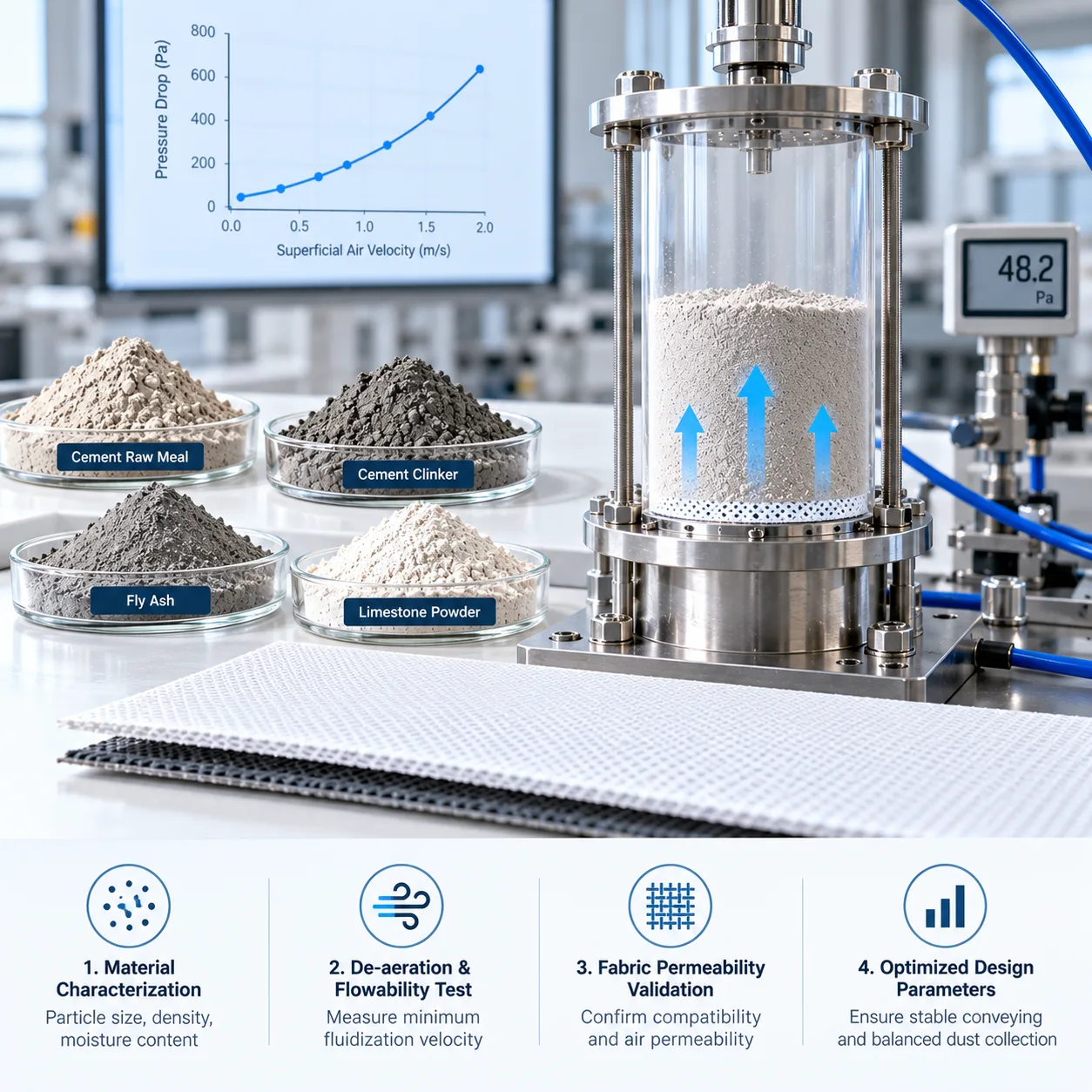
DARKO Powder Characterization & Fabric Permeability Testing
Industrial powders often exhibit subtle variations in flowability due to grinding circuit differences, chemical additives, and seasonal humidity. DARKO Cement Machinery eliminates project risk by conducting rigorous material de-aeration tests and permeable fabric compatibility validations before equipment fabrication, ensuring balanced venting into downstream pulse-jet dust collectors.
Air Slide Troubleshooting and Preventive Maintenance Protocols
Air gravity conveyors deliver remarkable operational availability due to the total absence of internal moving mechanical drives. However, minor variations in fluidization aerodynamics, blower air quality, or raw material moisture can trigger localized powder settling, aeration fabric blinding, and housing seal blowouts. Rapid diagnostic protocols and accurate root-cause identification are essential to maintain stable pseudo-fluid dry bulk transport across cement milling circuits, clinker distribution routes, and fly ash handling networks.
Sustaining continuous gravity-assisted flow above the permeable membrane demands an exact equilibrium between lower plenum static pressure, fluidizing air face velocity, and dust collection equipment venting drafts. DARKO Cement Machinery provides standardized troubleshooting frameworks and proactive inspection schedules to eliminate unscheduled outages, optimize process stability, and maximize the working life of fluidizing air slide installations.
Localized Powder Settling and Chute Clogging
Symptom Profile
Sudden bed stagnation, upstream material backup into bucket elevator boots or rotary valves, and dead settling zones visible through top inspection windows.
Root Cause Analysis
- Blower discharge pressure falls below the required 3000 to 5000 Pa operating threshold.
- Moisture condensation or washdown water pooling in lower air plenum chambers.
- Structural hanger deflection reducing the local conveyor slope below 4 degrees.
- Terminal venting exhaust duct plugging, creating severe downstream backpressure.
Corrective Action Plan
Verify blower discharge pressure and purge lower plenum drain taps. Clean de-dusting duct dampers and check structural support elevations with a digital inclinometer to restore design pitch.
Air Slide Fabric Blinding and Glazing
Symptom Profile
Aeration membrane hardens into an impermeable layer, aeration air volume declines sharply, and fine powder forms a solid crust across the fabric surface.
Root Cause Analysis
- Material moisture content exceeds the critical operational limit of 1.0% (optimum < 0.5%).
- Oil mist or moisture carryover from positive displacement blowers lacking filtration.
- Hydraulic false set of hot cement particles inside the interstitial weave pores.
- Thermal degradation of standard polyester fabric exposed to continuous loads above 150°C.
Corrective Action Plan
Replace blinded fabric sections immediately. Install secondary air intake coalescing filters and air dryers on blower supply lines. Upgrade high-temperature runs to specialized aramid woven media.
Flange Air Leakage and Fugitive Dust Emissions
Symptom Profile
Air hissing along longitudinal chute joints, localized powder spraying around sight glasses, and airborne fugitive dust accumulation in conveyor galleries.
Root Cause Analysis
- Thermal hardening, embrittlement, or aging of closed-cell silicone sealing gaskets.
- Uneven bolt torque or vibration-induced loosening of intermediate flange fasteners.
- Insufficient negative pressure exhaust draft at discharge terminal de-dusting points served by pulse-jet dust collectors.
- Over-pressurization of the upper material chamber caused by excessive blower CFM.
Corrective Action Plan
Cross-torque perimeter joint bolts to specified ratings. Replace degraded gaskets during planned outages. Adjust dampers connected to terminal baghouse dust collectors to sustain continuous slight negative draft (-50 to -100 Pa).
Preventive Maintenance Schedule and Field Checklist
Standardized operating inspection intervals engineered for 24/7 continuous bulk powder conveying lines.
| Subsystem Node | Frequency | Inspection Criteria | Acceptance Baseline | Standard Remediation |
|---|---|---|---|---|
| Blower Suction Filter | Weekly | Differential pressure gauge reading and particulate cake loading check | ΔP ≤ 1200 Pa | Pulse-jet clean element or replace intake filter cartridge |
| Fabric Tension and Surface | Monthly | Visual inspection for edge fraying, sagging, hardening, or crusting | Zero wrinkles, taut weave | Retension clamp bars or hot-swap damaged membrane sections |
| Plenum Condensation Drain | Weekly | Manual ball valve discharge check on lower aeration chambers | Zero moisture or oil residue | Drain condensate and inspect blower seals and upstream air dryers |
| Observation Glass and Seals | Bi-Weekly | Glass abrasion, internal powder scouring, frame bolt tightness | Clear visibility, zero dusting | Replace abraded tempered glass; renew silicone peripheral gaskets |
| Exhaust Vent Balance | Monthly | Static micro-manometer negative draft reading at de-dusting port | -50 to -150 Pa | Purge duct build-up and recalibrate butterfly throttling dampers |
| Structural Declination | Annual Outage | Digital inclinometer measurement across all conveyor spans | Designed ±0.2° (4°-8°) | Adjust threaded hanger rods and re-shim intermediate saddle supports |
Emergency Spare Parts for Cement Plant Turnarounds
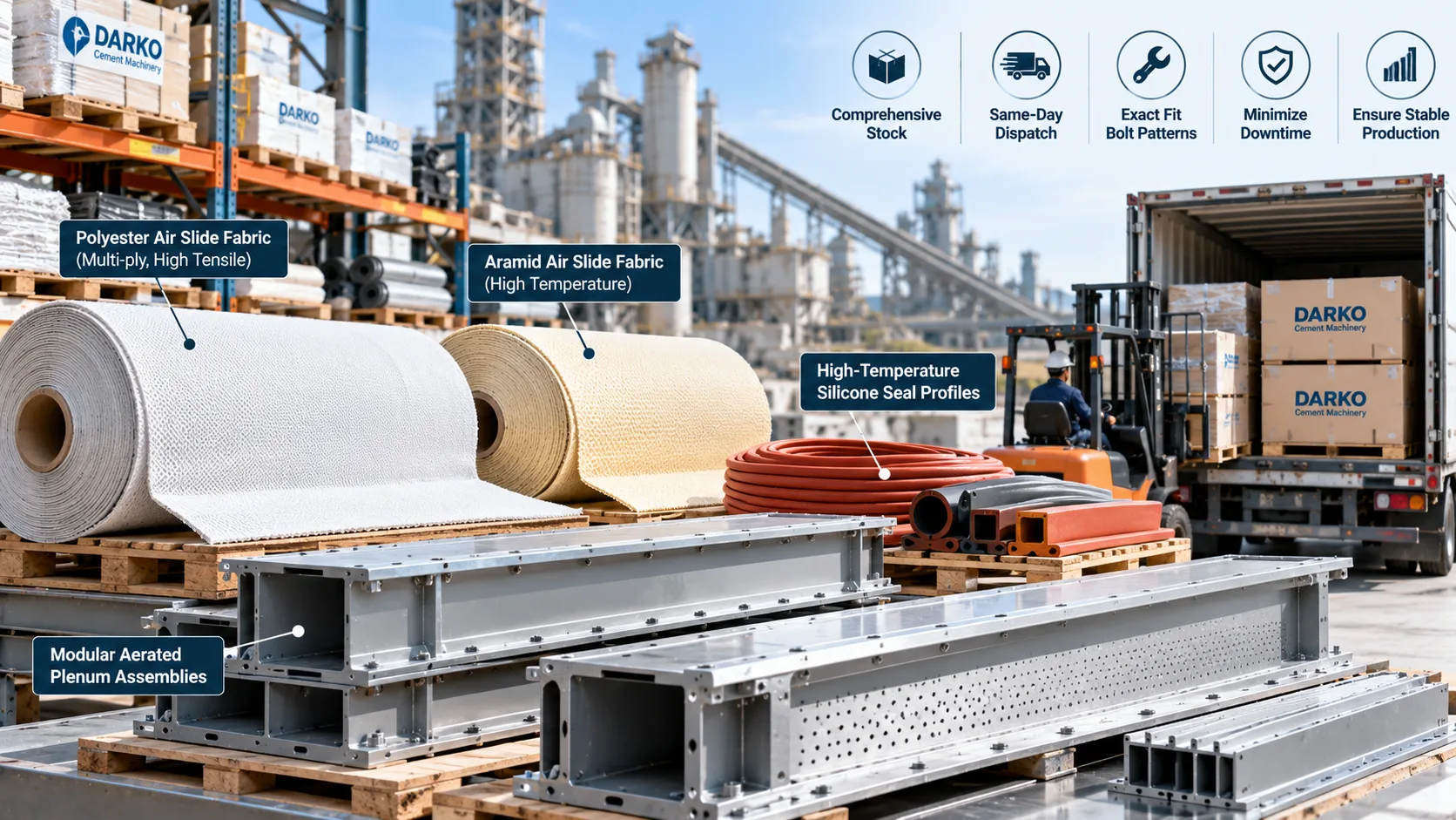
Unscheduled air slide downtime directly impacts raw grinding throughput and cement silo discharge rates. DARKO Cement Machinery maintains comprehensive off-the-shelf stock of high-tensile multi-ply polyester and aramid Air Slide Fabrics, high-temperature silicone seal profiles, and modular aerated plenum assemblies. All materials are precision-slit, heat-sealed, and pre-punched to exact bolt patterns for same-day dispatch and zero-delay installation.
Air Slide Conveyor Engineering FAQ: Calculations, Pressure Balancing, and System Design
Pneumatic gravity conveying relies on an exacting physical equilibrium among static aeration head pressure, superficial interstitial air velocities, and gravity decline angles. Below, DARKO Cement Machinery application engineers address mission-critical operational challenges, blower airflow calculations, venting requirements, and high-temperature component configurations encountered across cement, fly ash, and dry bulk processing facilities worldwide.
The selection between high-pressure centrifugal radial fans and rotary positive-displacement Roots blowers depends primarily on total conveying distance, distribution manifold geometry, and variable backpressure dynamics. Air gravity chutes operate on low-pressure pneumatic fluidization, generally requiring system operating static pressures between 3,000 Pa and 5,000 Pa (12 to 20 in. w.g. or 0.43 to 0.72 psi) across the permeable fabric boundary and overlying powder bed.
Centrifugal Radial Fans
Ideal for dedicated conveyor runs under 40 meters. They provide steady, oil-free, non-pulsating airflow at lower initial capital cost, significantly reduced decibel levels, and minimal routine motor and bearing maintenance.
Rotary Roots Blowers
Recommended for centralized multi-branch manifolds or extended single chutes exceeding 50 meters. Their positive displacement characteristic delivers constant volume flow regardless of upstream powder bed depth variations or fluctuating bed resistance.
When sizing blower air capacity, standard engineering rules prescribe an air consumption rate of 1.5 to 3.0 m³/m²·min (5 to 10 CFM/ft²) relative to the total active permeable fabric area. Roots blower installations should incorporate heavy-duty inlet air micro-filters, outlet silencers, check valves, and spring-loaded pressure relief valves to safeguard lower air chambers from over-pressurization.
Baseline Engineering Design Parameters
Standard empirical benchmarks referenced by DARKO engineers for sizing and evaluating heavy-duty industrial air gravity conveying systems:
Need customized fluidization airflow calculations, manifold pressure balance sizing, or high-temperature fabric retrofits?

Standard cross-section anatomy illustrating the upper dust-containment chute, permeable multi-ply membrane boundary, and pressurized lower air chamber.
Powder Fluidization Dynamics and Air Consumption Balance in Industrial Air Gravity Conveying
The smooth conveyance of dry bulk powders across an air gravity conveyor depends on transforming an otherwise consolidated granular mass into an aerated, flowing pseudo-fluid. In a stationary, non-aerated state, fine materials such as cement raw meal, Portland cement, and pulverized coal exhibit high internal friction angles and mechanical interlock. When low-pressure air passes through the engineered permeable fabric matrix at controlled superficial velocities, it forms microscopic air films around individual particles. This gas cushion effectively neutralizes inter-particle friction and eliminates sidewall sliding resistance, enabling the material to flow freely down slopes as shallow as 4 to 8 degrees under gravity.
Sustaining this fluid-like state requires an exact air consumption calculation. If superficial velocity falls below the minimum fluidization velocity (Umf), the bed de-aerates and settles onto the fabric, causing localized material build-up and conveyor blinding. Conversely, if superficial velocity approaches the terminal elutriation velocity (Ut), excessive air bubbles burst violently through the bed surface. This bubbling action throws dust into the upper headspace, accelerates wear on upper housing liners, and overburdens downstream baghouse dust collectors.
DARKO Cement Machinery engineers air gravity conveyors with calibrated pressure-drop profiles across both the permeable membrane and the material burden. By standardizing fabric air permeability resistance between 1,000 and 1,200 Pa under standard test conditions, the air slide fabric acts as an aerodynamic restrictor plate. This uniform flow distribution ensures dependable conveying performance across varying chute lengths and angles, delivering an energy-efficient transport solution that consumes less than one-fifth the operational power of conventional motorized screw conveyors.
Engineer a More Reliable Air Slide Conveying System
Planning a new installation or solving an existing conveying problem? Share your material, capacity, and layout requirements. DARKO can help review suitable air slide configurations, aeration requirements, and equipment options for your application.
From Powder Properties to Practical Equipment Selection.
Discuss chute dimensions, slope constraints, fluidizing fabric, blower selection, and dust extraction with DARKO's equipment team.
System Sizing Review
Conveying capacity, route length, available drop and material characteristics.
Equipment & Retrofit Options
Aeration media, airflow supply, access points and venting integration.
Request an Air Slide Engineering Review
Tell us the essentials. Additional drawings or technical files can be shared with our team after initial contact.
Need a broader conveying system or plant retrofit discussion? Our team can also assist with integrated bulk handling and dust collection applications.
Contact DARKO