
Engineering Configurations: Drop-Through, Blow-Through & Heavy-Duty Series
DARKO Cement Machinery manufactures application-tailored rotary airlock valves engineered to hold severe differential pressures, eliminate blow-by air leakage, and reliably discharge abrasive mineral powders across heavy industrial processes and integrated dust collection equipment systems.
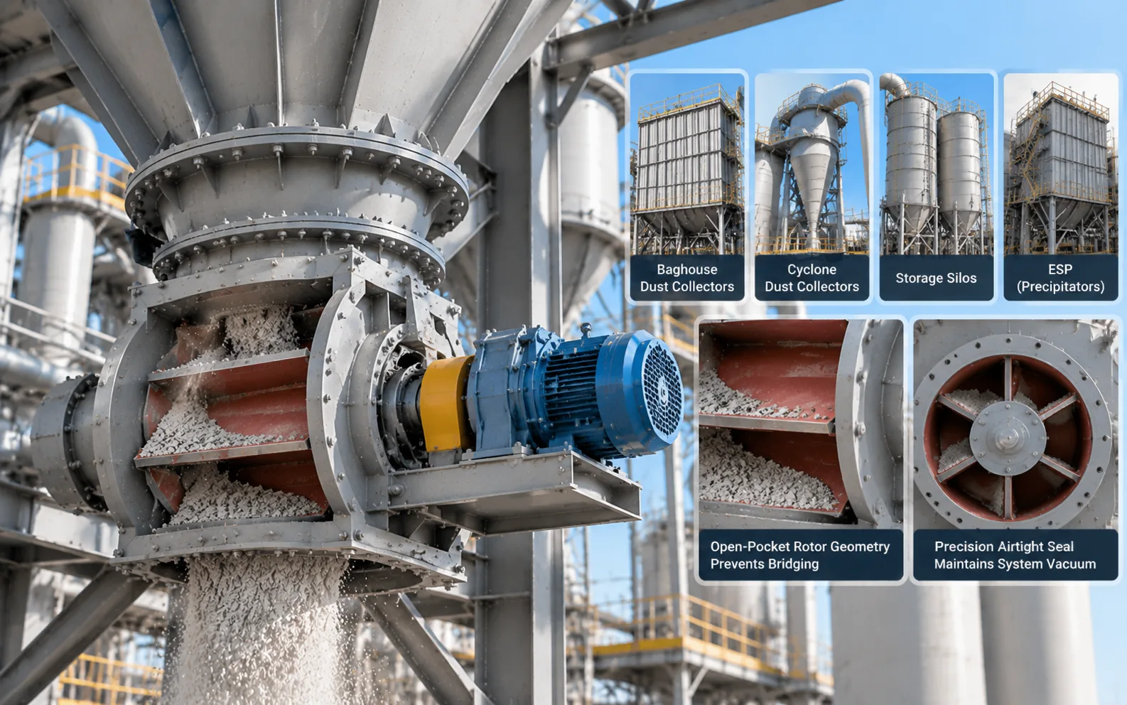
Drop-Through Rotary Airlock for Dust Hoppers, Cyclones & Storage Silos
The drop-through rotary airlock serves as the primary continuous discharge mechanism for gravity-fed bulk material systems. Bolted directly beneath industrial baghouse dust collectors, electrostatic precipitators, cyclone dust collectors, and storage silos, this design features precision open-pocket rotor geometry to maintain a dependable airtight seal while preventing powder bridging and dead-zone accumulation.
Standard DIN and ANSI 150# round or square flange interfaces available from DN150 to DN600 nominal diameter.
Direct-coupled cycloidal gearmotors, heavy-duty chain drives, and ATEX/IECEx explosion-proof variable frequency drives.
Raw meal, fly ash, ground limestone, kiln dust, bentonite, pulverized coal, and dry industrial minerals.
Cast iron (HT250), ductile iron (QT450), and 304/316L stainless steel for corrosive and abrasive applications.
- ✓ High Vacuum Isolation: Maintains differential pressure containment up to -0.05 MPa to prevent hopper blowback in dust filtration.
- ✓ Anti-Hangup Rotor Pockets: Radius-chamfered pocket roots promote complete gravitational product release on every revolution.
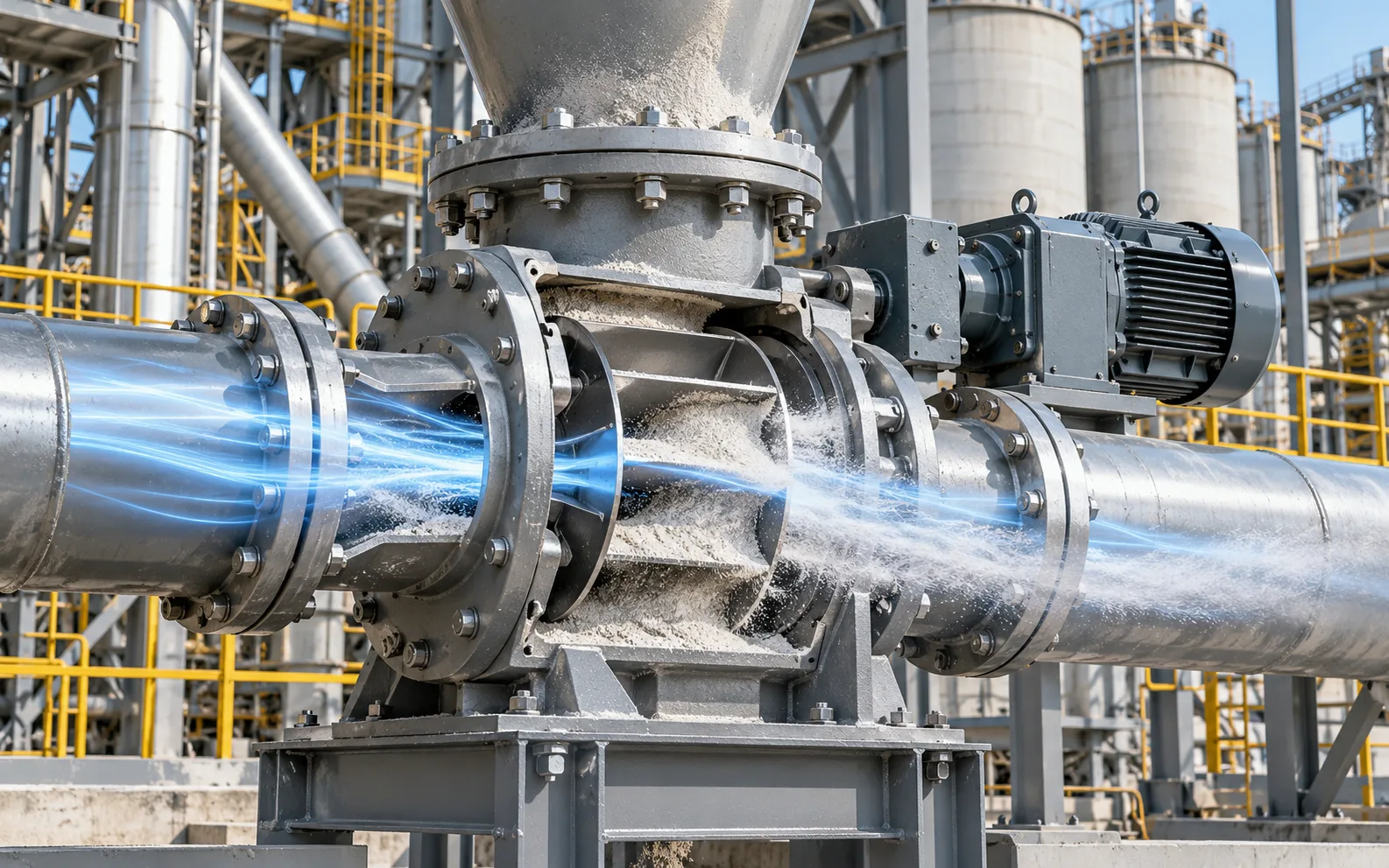
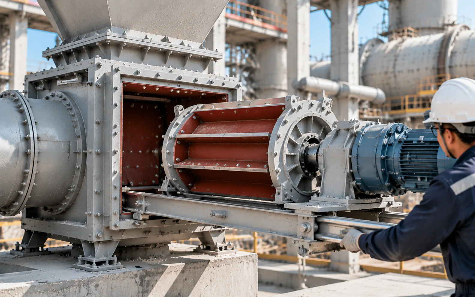
Precision CNC bored housing chambers and dynamically balanced rotors keep system air leakage under strict control.
Available in HT250 gray iron, QT450 ductile iron, 304/316L stainless steel, and Hardox-lined wear assemblies.
Engineered pressure boundaries suited for both deep-vacuum dust filtration and positive-pressure pneumatic lines.
Advanced Precision Engineering and Zero-Leakage Sealing Architecture
Differential pressure isolation in pneumatic conveying pipelines and hoppers across integrated dust collection equipment depends entirely on tight manufacturing tolerances and resilient shaft sealing systems. DARKO Cement Machinery engineers industrial rotary airlock valves to prevent reverse blow-by leakage, eliminate abrasive particulate ingress, and prevent rotor stalling under heavy powder loads. Every industrial rotary valve feeder incorporates CNC-machined radial clearances, outboard bearing isolation pedestals, and hardened wear interfaces engineered for continuous duty in abrasive cement and dry bulk handling systems.
CNC Machining & Micron Clearance Control
Housings and closed-end rotors are precision bored on multi-axis horizontal machining centers. Cold assembly clearances are held precisely between 0.08 mm and 0.10 mm (0.003–0.004 in). This ultra-tight rotor clearance minimizes parasitic air leakage across system differentials up to 1.5 bar (21.7 psi), maintaining conveyor efficiency and preventing hopper aeration.
- Radial Runout: Calibrated ≤ 0.02 mm
- Air Blow-By Reduction: Up to 68% over standard cast feeders
- Bore Finish: Ra 0.8 μm precision honed interior
Multi-Stage Packing & Outboard Isolation
Shaft penetrations feature multi-ring PTFE chevron V-packing paired with pressurized air purge channels that create a positive seal against micro-fine dust in high-efficiency pulse-jet dust collectors. Outboard self-aligning bearing pedestals are isolated from the end plates by an open atmospheric standoff gap, completely eliminating bearing contamination and thermal degradation.
- Shaft Seal Array: Multi-ring PTFE chevron with lantern ring
- Bearing Standoff: 50 mm atmospheric isolation zone
- Purge Air Pressure: 0.5–1.0 bar above line pressure
Anti-Shearing V-Inlet Geometry
Granular cement clinker, slag, and raw aggregates can wedge between the rotor vane tips and casing throat. DARKO integrates a precision V-shaped deflector shear rib and adjustable inlet scraper that direct bulk materials toward the center of rotor pockets, eliminating pinch points, motor over-torquing, and blade shearing.
- Torque Protection: Prevents granulate wedging and rotor stall
- Shear Deflector: Hardened alloy cutting edge replaceable bar
- Pocket Fill Rate: Uniform volumetric loading across vanes
Wear-Resistant Rotors & Hardened Surfaces
To withstand continuous handling of abrasive raw meal, silica sand, and fly ash discharged from heavy-duty baghouse dust collectors, rotor tips accommodate adjustable, replaceable scraper blades in Hardox 500, polyurethane, or tungsten carbide overlays. Internal casing bores and side cover plates receive high-velocity oxygen-fuel (HVOF) tungsten carbide cladding or hard chrome plating.
- Blade Adjustability: Slotted radial adjustment for wear reset
- Surface Hardening: HVOF tungsten carbide or hard chrome plating
- Wear Life: Up to 3.5x longer service life than standard cast iron
Factory Quality Testing & Differential Pressure Validation
Every rotary airlock valve manufactured by DARKO Cement Machinery complies with rigorous ISO 9001 certified quality control procedures before leaving our manufacturing facility. Rotors undergo two-plane dynamic balancing to ISO 1940 G2.5 standards to eliminate harmonic vibration across all operational speed ranges. Fully assembled airlock bodies undergo 100% static pressure hold testing to verify housing soundness, side plate gasket sealing, and packing gland integrity under elevated differential pressures.
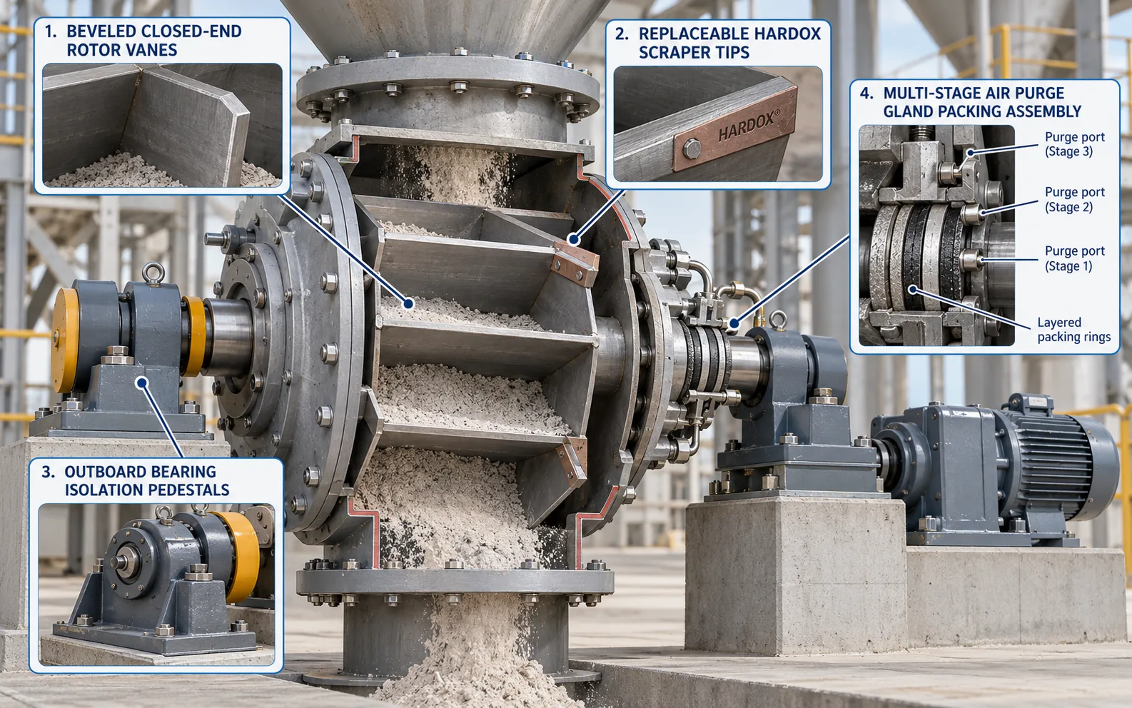
Engineering schematic: Beveled closed-end rotor vanes, replaceable Hardox scraper tips, outboard bearing isolation pedestals, and multi-stage air purge gland packing assembly.
Proven Applications Across Cement & Heavy Bulk Handling Systems
Engineered for aggressive continuous duty cycles, DARKO rotary airlock valves serve as critical pressure barriers and volumetric metering devices across primary dry bulk processing lines. By combining calibrated rotor clearances with dynamic shaft air purging, these heavy-duty feeders resolve differential pressure losses and prevent abrasive powder fluidization across integrated dust collection equipment and plant processing interfaces.
Dust Collector Hopper Airlocks
Operating beneath negative-pressure baghouse dust collectors, bin vent filters, and high-efficiency cyclone dust collectors, a dust collector rotary valve must discharge separated fines without allowing reverse atmospheric infiltration. Uncontrolled intake air disrupts internal airflow profiles, decreases collection efficiency, and causes severe re-entrainment of fine particles into the clean gas chamber.
Operating Challenge & Solution
Silo Discharge & Volumetric Metering
Raw meal, finished cement, and fine fly ash stored in tall storage silos frequently experience core aerated fluidization, causing sudden flushing that overwhelms downstream conveyors. Applying a cement silo airlock discharge valve at bottom transition cones guarantees steady, pulse-free volumetric dosing directly into downstream transport systems.
Operating Challenge & Solution
Pneumatic Conveying Injection
Injecting dry mineral bulk solids into pressurized dilute-phase or dense-phase transport pipelines requires tight clearance containment. A specialized pneumatic conveying airlock prevents pressurized carrier air from blowing upward into the feed silo, ensuring continuous forward material delivery at pipeline pressures reaching 1.5 bar.
Operating Challenge & Solution
Engineered Synergy Across Complete Process Conveying Lines
Rotary airlocks do not operate in isolation. DARKO Cement Machinery builds rotary valves specifically configured to integrate with auxiliary upstream and downstream processing machinery. Whether matching standard DIN/ANSI round flanges or adapting to legacy rectangular transitions, our equipment designs eliminate material hang-up, streamline structural footprint, and simplify maintenance accessibility.
- Fabric Baghouse Systems Maintains hopper vacuum integrity under peak dust collection loads.
- Air Slide Conveyors Delivers controlled volumetric mass flow directly onto aeration fabrics.
- Bin Vent Filters Seals silo exhaust ports against ambient moisture and reverse venting.
- Screw Conveyor Transitions Eliminates back-pressure venting and throat bridging at transfer points.
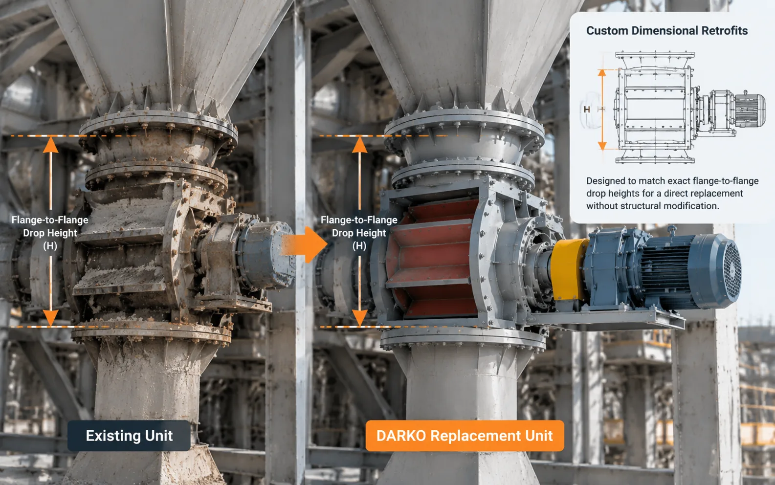
Custom Dimensional Retrofits: DARKO designs replacement units matching exact flange-to-flange drop heights to upgrade existing plant nodes without structural modification.
Rotary Airlock Valve Specifications & Capacity Sizing Chart
Select standard rotary airlock feeders by volumetric displacement, flange diameter, and operating speed. Engineered for cement plants, pulverized coal systems, and pneumatic conveying lines alongside heavy-duty dust collection equipment, DARKO rotary airlocks maintain precision differential pressure containment across wide throughput requirements.
Interactive Feeder Sizing Tool
Enter bulk material density and target mass flow to determine the matching valve displacement, recommended rotor speed, and nominal flange size.
| Model | Flange Pattern | Displacement (L/rev) | Rotor Speed (RPM) | Capacity Range (m³/h) | Drive Power (kW) | Max Diff. Pressure | Max Temp Rating |
|---|---|---|---|---|---|---|---|
| DK-RAV 150 | DN150 (6") | 2.5 | 15 – 35 | 1.8 – 4.2 | 0.75 | 1.5 bar (21.8 psi) | 250 °C (482 °F) |
| DK-RAV 200 | DN200 (8") | 6.0 | 15 – 35 | 4.3 – 10.0 | 1.10 | 1.5 bar (21.8 psi) | 250 °C (482 °F) |
| DK-RAV 250 | DN250 (10") | 12.5 | 15 – 32 | 9.0 – 19.2 | 1.50 | 1.5 bar (21.8 psi) | 280 °C (536 °F) |
| DK-RAV 300 | DN300 (12") | 25.0 | 15 – 30 | 18.0 – 36.0 | 2.20 | 1.5 bar (21.8 psi) | 300 °C (572 °F) |
| DK-RAV 400 | DN400 (16") | 60.0 | 12 – 28 | 43.2 – 100.8 | 4.00 | 2.0 bar (29.0 psi) | 350 °C (662 °F) |
| DK-RAV 500 | DN500 (20") | 115.0 | 10 – 25 | 69.0 – 172.5 | 7.50 | 2.0 bar (29.0 psi) | 400 °C (752 °F) |
| DK-RAV 600 | DN600 (24") | 200.0 | 10 – 22 | 120.0 – 264.0 | 15.00 | 2.0 bar (29.0 psi) | 450 °C (842 °F) |
Volumetric Fill Efficiency
Theoretical throughput values reflect a 0.75 to 0.85 pocket fill factor. For highly aerated materials like raw meal or pulverized fly ash collected beneath baghouse dust collectors, actual fill efficiency may vary with venting and pressure balance.
Bulk Density Flexibility
Engineered gear reducers and VFD-compatible drives accommodate material densities from 0.5 to 2.2 t/m³, ensuring sufficient starting torque during surge feed or hopper head loads.
Custom Drop-In Retrofits
DARKO manufactures custom flange-to-flange heights and bolt hole patterns (ANSI, DIN, JIS) to replace legacy or obsolete third-party units across our engineered products line without costly chute or structure rework.
How to Select the Right Airlock: Engineering Guide and Valve Comparison
Selecting the appropriate dry bulk isolation valve dictates system run-time, pneumatic conveying stability, and particulate emission control. Differential pressure dynamics, particle abrasiveness, thermal rotor expansion, and continuous discharge uniformity demand a disciplined selection methodology. Backed by over two decades of cement plant and dry bulk handling engineering, DARKO provides complete valve sizing reviews, pressure loss evaluations, and rotor pocket fill factor optimizations to prevent blow-by leakage, bridging, and premature rotor wear across plant-wide bulk conveying equipment.
Four Core Selection Criteria for Bulk Material Handling
Every dry powder or bulk solids process introduces distinct operational variables. Evaluating these four engineering factors ensures the selected airlock feeder sustains tight pressure boundaries, minimizes parasitic gas losses, and delivers reliable volumetric throughput under continuous load.
Differential Pressure
Determines counter-flow air leakage and shaft sealing design. Systems operating across differential pressures up to 1.5 bar (21.8 psi) require tight 0.08–0.12 mm rotor-to-body clearances, multi-pocket shroud profiles, and pressurized air purges to prevent blow-back from disrupting feeder intake.
Particle Abrasiveness & Size
Fine, fluidizable raw meal requires precision-machined rotor blades to mitigate slip-through, while abrasive cement clinker, fly ash, and quartz require replaceable Hardox wear liners, hardened rotor tip bevels, and anti-shearing V-inlet deflectors to eliminate mechanical jamming.
Continuous Temperature
Elevated process temperatures cause uneven thermal expansion between the rotor vane assembly and stationary casing. Pre-engineered thermal hot-clearance machining, outboard self-aligning bearing pedestals, and lantern ring cooling jackets are mandatory for applications from 150°C up to 450°C.
Discharge Uniformity
Continuous rotary feeders provide steady, pulse-free volumetric feed into downstream air gravity conveyors, pneumatic transfer lines, and grinding circuits, preventing pressure surges, cyclone carryover, and downstream combustion imbalances.
Comparative Evaluation: Rotary Airlock vs. Double Flap vs. Slide Gate
Selecting the optimal bulk material valve requires matching mechanical configuration to operating pressure, material flow characteristics, and maintenance profiles. Review the engineering matrix below to understand the functional boundaries of rotary airlocks, cyclic double flap valves, and static shutoff slide gates.
| Valve Technology | Feeding Dynamic | Pressure Rating | Max Operating Temp | Material Granulometry | Primary Plant Role |
|---|---|---|---|---|---|
| Rotary Airlock Valve (DARKO Series) | Continuous, pulse-free rotary volumetric feeding | High continuous dynamic sealing (up to 1.5 bar) | Up to 450°C with engineered thermal clearance | Fine powders, aerated meal, micro-granules (≤ 10 mm) | Baghouse hopper discharge, pneumatic line injection, silo dosing |
| Double Flap Gate Valve | Intermittent, batch cyclic gravity discharge | Moderate differential sealing via alternate mechanical flaps | Up to 800°C+ (cast heat-resistant alloy construction) | Coarse lumps, jagged clinker, abrasive rocks (up to 100 mm) | Preheater cyclone stages, kiln dust discharge, clinker coolers |
| Knife / Slide Gate Valve | Static on/off shutoff or manual flow trimming | Static boundary isolation; no dynamic differential sealing | Up to 600°C depending on blade alloy and packing seal | Universal dry bulk solids and aerated powders | Emergency equipment isolation, maintenance shutoff beneath silos |
Step-by-Step Sizing and Capacity Selection Roadmap
Standardized sizing prevents drive motor tripping, premature rotor scouring, and excessive pocket air blow-by. Follow this four-step engineering sequence when specifying rotary airlock valves for cement plants, fly ash systems, and mineral dry bulk processing.
Throughput & Bulk Density
Calculate volumetric capacity (m³/h) from target mass flow (t/h) using the material's aerated bulk density, accounting for aeration settling behavior in hoppers.
Pocket Filling Efficiency
Apply realistic rotor pocket fill factors (typically 70% to 85% for aerated powders). Sizing above 85% causes inlet throat bridging, material shearing, and erratic discharge.
Rotor Speed & Tip Velocity
Determine operational drive speed (optimal 15 to 25 RPM). Speeds exceeding 30 RPM increase vane wear, induce displacement blow-by, and reduce pocket filling efficiency.
Clearance & Wear Hardening
Specify radial rotor clearances (0.08 to 0.12 mm). Add hard-chrome bore plating, tungsten carbide tip scrapers, and outboard air purges based on system abrasiveness and differential pressure.
Need Process Calculation or Custom Flange Adaptation?
Backed by over 20 years of cement fluid dynamics engineering, DARKO provides comprehensive valve sizing analyses, differential pressure loss simulations, and drop-height retrofit engineering. Whether replacing existing leaky feeders or designing new pneumatic conveying systems, our engineering specialists ensure seamless mechanical integration and long service life.
- ✓1:1 Flange-to-flange direct retrofit drawings
- ✓Dynamic leakage and blow-by rate calculation
- ✓High-temperature thermal clearance compensation
- ✓Heavy-duty wear liner and hardfacing options
Contact our engineering team for project-specific sizing and retrofit support.
Frequently Asked Questions: Operation, Leakage Control & Maintenance
Pneumatic bulk conveying equipment and heavy-duty dust collector hoppers require reliable rotary airlock valves capable of sustaining stable volumetric throughput, tight differential pressure boundaries, and continuous abrasive resistance. Review technical operating guidelines covering hot-running thermal clearance compensation, rotary valve air leakage troubleshooting, and field-proven rotor maintenance practices developed by DARKO Cement Machinery.
Thermal seizure occurs when rapid temperature increases up to 450°C cause the rotor assembly to expand at a different rate than the external cast housing, closing running clearances. DARKO Cement Machinery eliminates rotor binding through precise thermal growth calculations combined with dedicated high-temperature structural engineering:
- Pre-Calculated Hot-Running Clearances: Radial tip gaps and axial side-plate tolerances are precision-machined for the operating thermal equilibrium, stabilizing at a nominal 0.10 mm clearance under continuous heat.
- Axial Expansion Compensation: Drive shafts incorporate floating outboard spherical roller bearings and axial expansion relief pockets to absorb linear rotor shaft elongation without stressing end-plates.
- External Jacketing & Thermal Isolation: High-temperature applications feature cooling water jackets, stand-off bearing brackets, and graphite-impregnated gland packing to block heat transmission to mechanical drives.
- Flexible Rotor Blade Profiles: Adjustable, heat-treated alloy or spring-loaded wiper blades compensate for transient thermal shocks, preventing mechanical jamming during sudden process upsets.
Operational Guideline: Always pre-heat high-temperature airlocks gradually during line startup before introducing full clinker or calcined mineral feed rates.
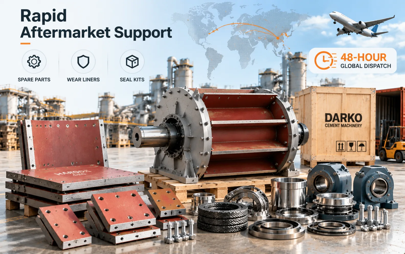
Rapid Aftermarket Support & Field Kits
Minimize unplanned conveying downtime. DARKO Cement Machinery maintains dedicated spare inventory with 48-hour global dispatch for precision-balanced replacement rotors, replaceable Hardox wear liners, and high-temperature seal kits.
Need Scheduled Overhaul Protocols?
Access standardized maintenance checklists, fastener torque schedules, and differential leakage verification procedures tailored for cement kiln lines, grinding circuits, and terminal silos.