Anatomy of a Parallel Slide Gate Valve
To understand parallel slide gate valve operation, we must first look at the core components inside the body. Unlike traditional wedge gates, this design relies on flat, parallel sealing surfaces that slide across one another. Every component works together to handle extreme differential pressures and thermal cycles without mechanical jamming.
Two Parallel Sliding Discs and Internal Spring Mechanism
At the heart of the assembly, we use two independent, free-floating discs rather than a single solid wedge:
-
- Spring-loaded valve discs: A central spring mechanism—typically stainless steel or Inconel coil springs or Belleville washers—sits sandwiched between the two discs.
- Pre-load sealing: This internal spring keeps both disc faces in constant contact with the body seats, maintaining an initial seal even at low line pressures.
- Independent movement: Because the discs are not rigidly joined, each disc adjusts dynamically to line pressure and thermal expansion.
Upstream and Downstream Parallel Seats
The valve body houses two parallel seats positioned perpendicular to the flow bore:
-
- Parallel disc and seat arrangement: The faces are machined flat and parallel, completely eliminating the mechanical wedging forces found in wedge valves.
- Bi-directional sealing capability: While line fluid pressure primarily energizes the downstream disc against the downstream seat, the upstream seat remains supported by the internal springs.
- Wiping action: During travel, the discs slide directly across the seat faces, shearing away scale, rust, and particulate matter before the valve seats fully.
Rising Stem and Packing Chamber Design
We rely on a precision-machined rising stem to deliver smooth, predictable travel:
-
- Clear visual indication: The rising stem provides an instant, external confirmation of valve position, which matches what you see in a standard parallel slide gate valve animation.
- Stem-to-disc engagement: The stem connects to a disc carrier that pulls or pushes the discs without applying wedging torque at the bottom of the stroke.
- High-integrity packing chamber: A deep stuffing box packed with high-purity flexible graphite rings ensures zero external stem leakage in high-pressure steam isolation duties.
Integrated Bypass Equalizing System
High-differential pressures create substantial friction across the seat faces. We integrate a bypass line to maintain reliability:
-
- Pressure equalization: Opening the small bypass valve balances fluid pressure across the upstream and downstream sides before the main discs lift.
- Reduced operating torque: Equalizing the differential pressure dramatically lowers the required actuator or handwheel thrust.
- Seat protection: Eliminating extreme frictional drag during initial opening prevents seat galling and extends component lifespan in high-velocity steam lines.
How Parallel Slide Gate Valve Operation Works
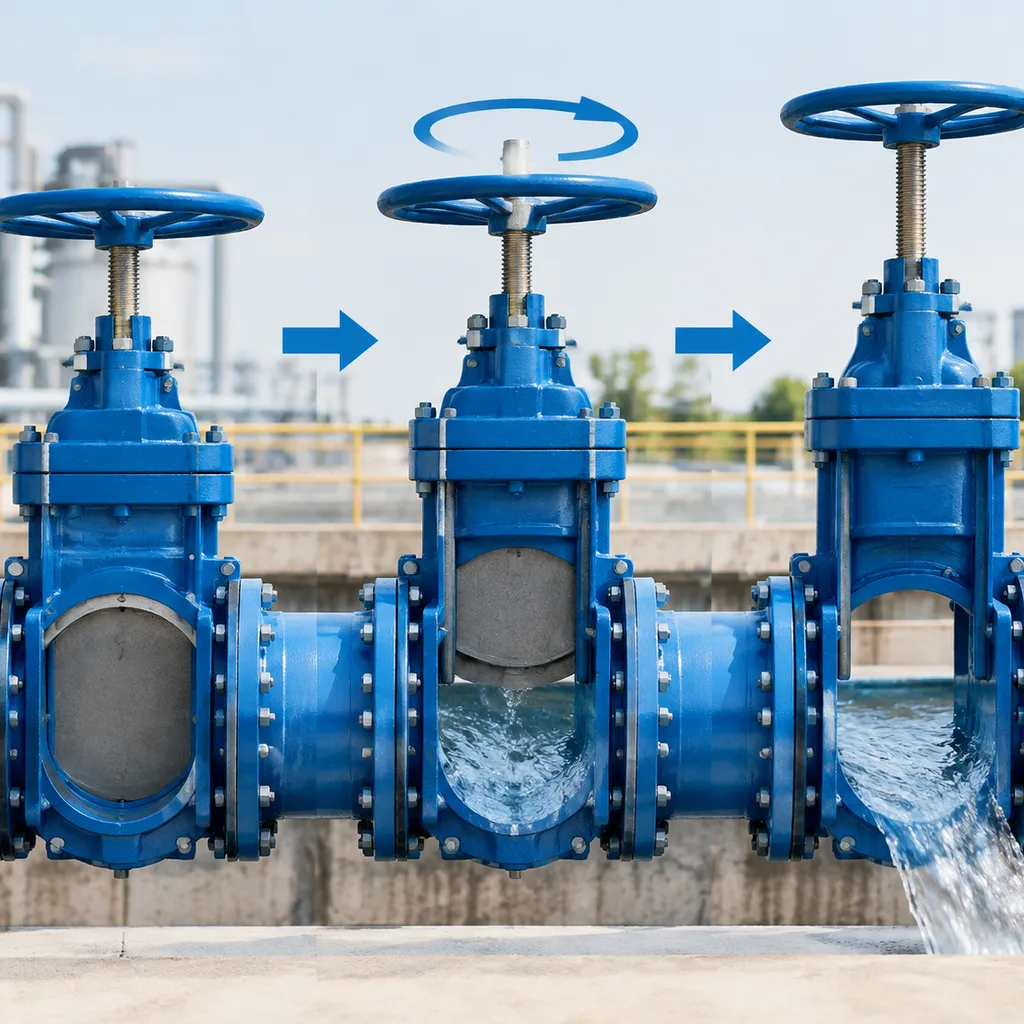
Understanding parallel slide gate valve operation comes down to one core concept: we do not wedge parts together to force a seal. Instead, we let fluid mechanics and internal mechanics do the heavy lifting.
Position Seating vs. Torque Seating Dynamics
Conventional wedge gates rely on torque seating—driving a wedge deep into an angled seat pocket with massive actuator thrust. Parallel slide designs run on position seating.
-
- Travel-driven shut-off: The stem drives the disc assembly directly to a mechanical travel limit rather than wedging it tight.
- Reduced stem strain: Because the valve does not require excess torque to seal, actuator wear drops and the stem threads last far longer.
- Zero wedging damage: Sealing surfaces glide parallel to one another, preventing the gouging and localized stress common in wedge setups.
Initial Contact and Line-Pressure-Energized Sealing
Sealing occurs in two distinct, sequential stages:
-
- Spring-loaded initial contact: At low or zero differential pressure, internal disc springs supply continuous pre-load. This keeps both parallel sliding discs in direct, flat contact with the upstream and downstream seat faces, preventing media bypass.
- Line-pressure energization: As fluid pressure rises, the upstream media acts directly against the upstream disc face. This internal pressure bypasses the upstream disc and exerts full line force behind the downstream disc, pressing it firmly into the downstream seat ring.
The higher the differential pressure in the line, the tighter the downstream seal becomes. This line pressure energized sealing provides tight isolation across our industrial slide gate valves without requiring external operator force.
Thermal Expansion Handling Without Mechanical Binding
Thermal binding is a constant failure point for wedge designs in severe steam and thermal cycling lines. When hot fluid enters a closed wedge gate, the metal components expand unevenly, pinching the wedge permanently into the seat body.
The parallel slide gate valve operation eliminates this hazard completely:
-
- Floating disc design: The dual discs float independently within the carrier.
- Free axial movement: Thermal expansion simply flexes the internal spring slightly without transferring mechanical stress to the seats or stem.
- Effortless reopening: Even after rapid temperature spikes or cool-downs, the valve opens smoothly under standard actuator torque without sticking or galling.
Parallel Slide Gate Valve Animation Breakdown
Watching a parallel slide gate valve animation gives you an immediate look at how fluid forces and mechanical clearance interact inside the body. In our technical modeling and shop tests, we break down this movement into four distinct stages to demonstrate true parallel slide gate valve operation.
Visualizing the Opening Sequence and Disc Retraction
When the actuator rotates the rising stem, the disc carrier lifts vertically without any lateral wedging:
-
- Initial stem lift: The carrier moves upward, relieving mechanical force before the discs break contact with the body seats.
- Spring-guided sliding: The internal spring keeps both discs flat against the seats, preventing flutter or tilting during vertical travel.
- Full bore clearance: As the discs fully retract into the bonnet, the pipeline achieves an unobstructed, round bore identical to the pipe ID.
Mid-Stroke Fluid Flow and Turbulence Patterns
A cross-sectional parallel slide gate valve 3d animation clearly highlights the shift in internal flow dynamics during throttling or cycling:
-
- High-velocity vena contracta: As the disc edge clears the seat bore, fluid rushes through a crescent-shaped opening, generating localized turbulence.
- Erosion mitigation: Because the discs do not wedge into a pocket, high-velocity steam or slurry passes cleanly across the flat seat rings rather than chewing out a tight mechanical groove.
- Balancing system dynamics: In facilities running parallel slide units alongside quick-acting butterfly valves for flow balancing, this smooth mid-stroke travel limits pressure shocks across upstream equipment.
Closing Stroke: Disc Wiping Action Across Seat Faces
During the downward closing stroke, the parallel design actively protects its own sealing surfaces:
-
- Continuous surface contact: Both discs slide in full contact with the parallel body seats throughout travel.
- Self-cleaning wiping effect: This sliding motion pushes aside scale, rust particles, and foreign solids, clearing the seats before full closure.
- Absence of jamming: Without a tapered wedge driving downward, there is zero risk of mechanical sticking at the bottom of the stroke.
Internal Pressure Distribution During Complete Shut-Off
Once the gate reaches the bottom limit, the parallel disk gate valve operation relies on system energy rather than mechanical torque to seal:
-
- Upstream disc response: Upstream line fluid enters the valve cavity, equalizing pressure behind both discs.
- Downstream fluid-energized seal: Line pressure drives the downstream disc firmly against the downstream seat ring, creating a bubble-tight barrier.
- Low-pressure retention: The central spring maintains uniform baseline contact on the upstream face, ensuring complete shut-off even before full line differential builds up.
Parallel Slide vs Wedge Gate Valve Operation
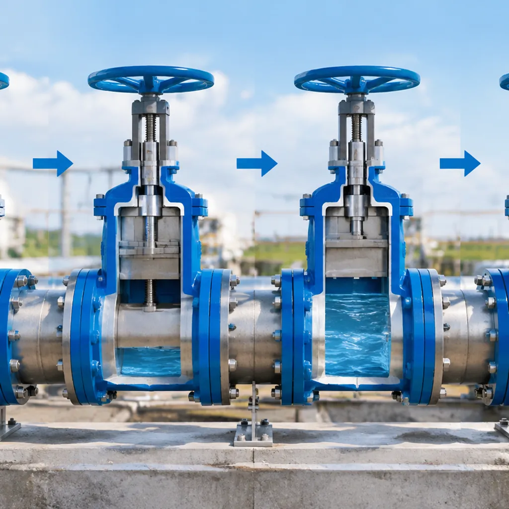
Thermal Binding and Wedging Risk Comparison
-
- Flexible/Solid Wedge Gates: These rely on mechanical force to drive a tapered gate between angled body seats. During hot shutdowns, cooling metal shrinks around the wedged disc, causing severe thermal binding. When you try to reopen the line, stems shear or actuators trip on overload.
- Parallel Slide Design: We use two independent, spring-loaded discs sliding parallel across flat seat faces. Because discs adjust freely between the seats, changes in pipe temperature cannot jam the assembly. This makes thermal binding prevention effortless without needing external expansion compensators.
Torque Requirements During Open and Close Cycles
The operating mechanics drastically change how much torque your actuator needs to deliver:
| Operational Metric | Wedge Gate Valve | Parallel Slide Gate Valve |
|---|---|---|
| Seating Mechanism | Torque-seated (wedging force) | Position-seated (fluid line pressure) |
| Opening Breakaway Torque | Extremely high (must unseat wedge) | Low (only dynamic friction to overcome) |
| Closing Seating Torque | High (stems driven hard into seats) | Low (discs drop into travel limits) |
| Actuator Size Required | Heavy-duty, high output | Compact, lower thrust output |
Because parallel slide gate valve operation relies on upstream-to-downstream fluid differential rather than brute stem force to seal, total seating and unseating torque remains consistent throughout the entire stroke.
Seat Wear Patterns and Long-Term Durability in Steam Service
In high-pressure steam isolation, wedge valves suffer from uneven seat contact and point-load scoring every time the wedge drives home.
By contrast, our parallel slide arrangement delivers a distinct wiping motion across both seat faces during every travel stroke. This self-cleaning action sweeps away scale, iron oxide, and foreign particulates instead of crushing debris into the seating area.
-
- Fluid velocity stays evenly distributed across the flat faces during cycling.
- Seat rings wear evenly and flat, rather than grooving or distorting.
- Discs retain continuous face contact, eliminating high-velocity steam wire-drawing that destroys standard wedge seats.
Troubleshooting Operational Failures
Even with a self-cleaning design, harsh service conditions can disrupt proper parallel slide gate valve operation. When line debris or mechanical fatigue sets in, systematic troubleshooting gets your line back up to standard shut-off performance without unnecessary downtime.
Resolving Disc Seat Scoring and Particulate Build-Up
Fine particulates and scale can occasionally become trapped between the sliding surfaces, leading to through-seat leakage:
Flush before cycling: High-velocity steam or fluid flushing clears dislodged solids before running a complete closing cycle.
Inspect the seat faces: Look for parallel scratch tracks across the seating plane. Minor galling can be lapped in-line, while deep scoring requires disc and seat replacement.
Confirm full stroke travel: Build-up in the valve cavity bottom can block downward travel, preventing the discs from reaching the precise sealing position.
Stem Packing Leakage Fixes and Gland Adjustments
Steam cuts and fugitive emissions around the rising stem indicate packing box degradation:
Even torque application: Tighten the gland eyebolts evenly by a quarter-turn at a time. Uneven gland torque cocks the follower, accelerating packing friction and stem wear.
Check stem runout: Stroke the valve and verify the stem travels straight without binding against the yoke bushings.
Repack under scheduled isolation: If gland adjustment bottoms out, replace the graphite packing rings and ensure lantern rings align properly with leak-off ports.
Diagnosing Central Spring Degradation and Loss of Pre-Load
The internal spring pack maintains initial mechanical contact before line pressure assists the seal. When internal springs lose temper or crack:
Low-pressure bypass leakage: If the valve seals tight under maximum operating pressure but weeps during low-pressure line fill, the central disc springs have lost tension.
Rattling or erratic travel: As seen in a standard parallel slide gate valve animation, discs must remain stable during transit. Missing pre-load allows discs to flutter against seat faces during mid-stroke cycling, causing rapid chatter wear.
Spring replacement: Disassemble the disc carrier during major overhauls, check free spring height against manufacturer tolerances, and replace the spring set immediately if relaxation exceeds limits.
Frequently Asked Questions
Why does a parallel slide gate valve eliminate thermal jamming?
Traditional wedge valves often lock up when line temperatures surge because the metal wedge expands directly into the tapered body seats. In contrast, parallel slide gate valve operation relies on two flat, parallel discs that float freely inside a carrier. When thermal expansion occurs, the discs simply expand outward parallel to the seat faces without mechanical pinching. We never have to worry about cold-cracking or stuck stems during extreme thermal cycles.
Does a parallel slide gate valve offer bi-directional isolation?
Yes, it delivers dependable bi-directional shut-off. A typical parallel slide gate valve animation shows that while line pressure actively forces the downstream disc against its seat ring to establish a primary seal, the upstream disc remains in position. If line flow reverses, the pressure differential simply pushes the opposite disc against the other seat, maintaining an equally tight seal in reverse flow directions.
What role does the central disc spring play in low pressure?
At zero or low operating pressures, system fluid lacks the force needed to energize the downstream seal. The internal disc spring supplies continuous mechanical pre-load to bridge that gap:
Initial Contact: Keeps both disc faces seated against the body rings to prevent initial weeping.
Debris Clearing: Maintains sliding contact during movement so discs wipe particulate away cleanly.
Alignment: Stabilizes the internal assembly when handling heavy flow shifts across upstream systems and related storage discharge equipment.
How does fluid velocity affect disc wear during cycling?
These are on-off isolation valves, not throttling devices. If we cycle the valve through mid-stroke too slowly under high fluid velocity, localized turbulence can cause wire-drawing across the seat faces and disc flutter. Ensuring rapid, decisive actuation keeps the sliding surfaces protected inside the body neck and out of high-velocity erosion zones.