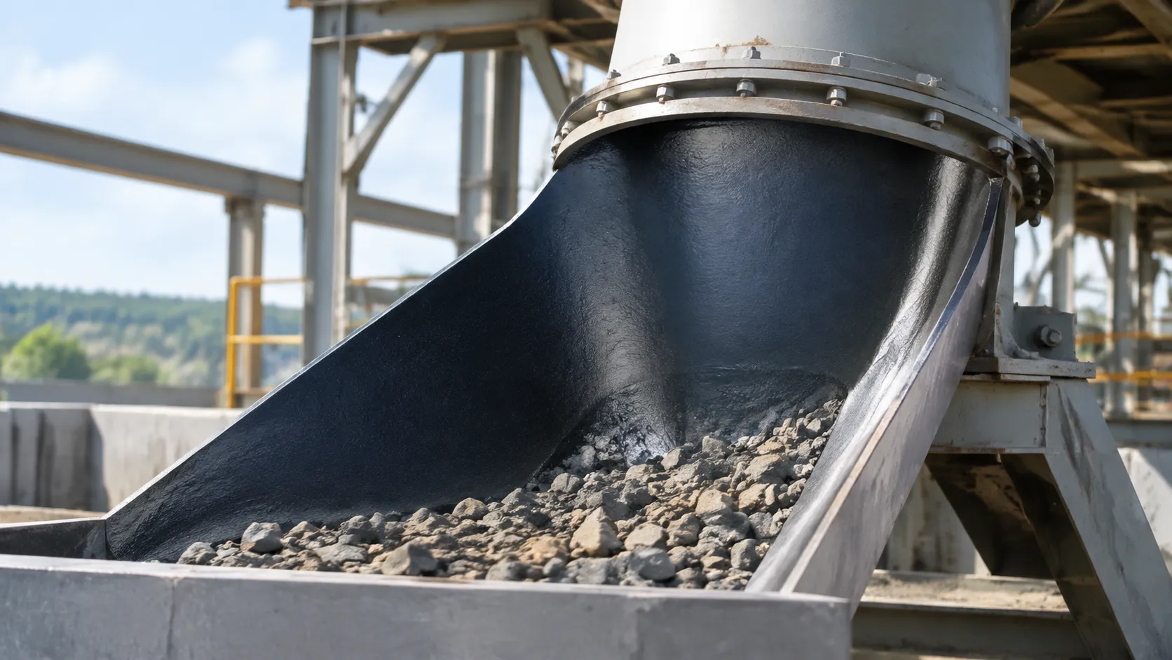
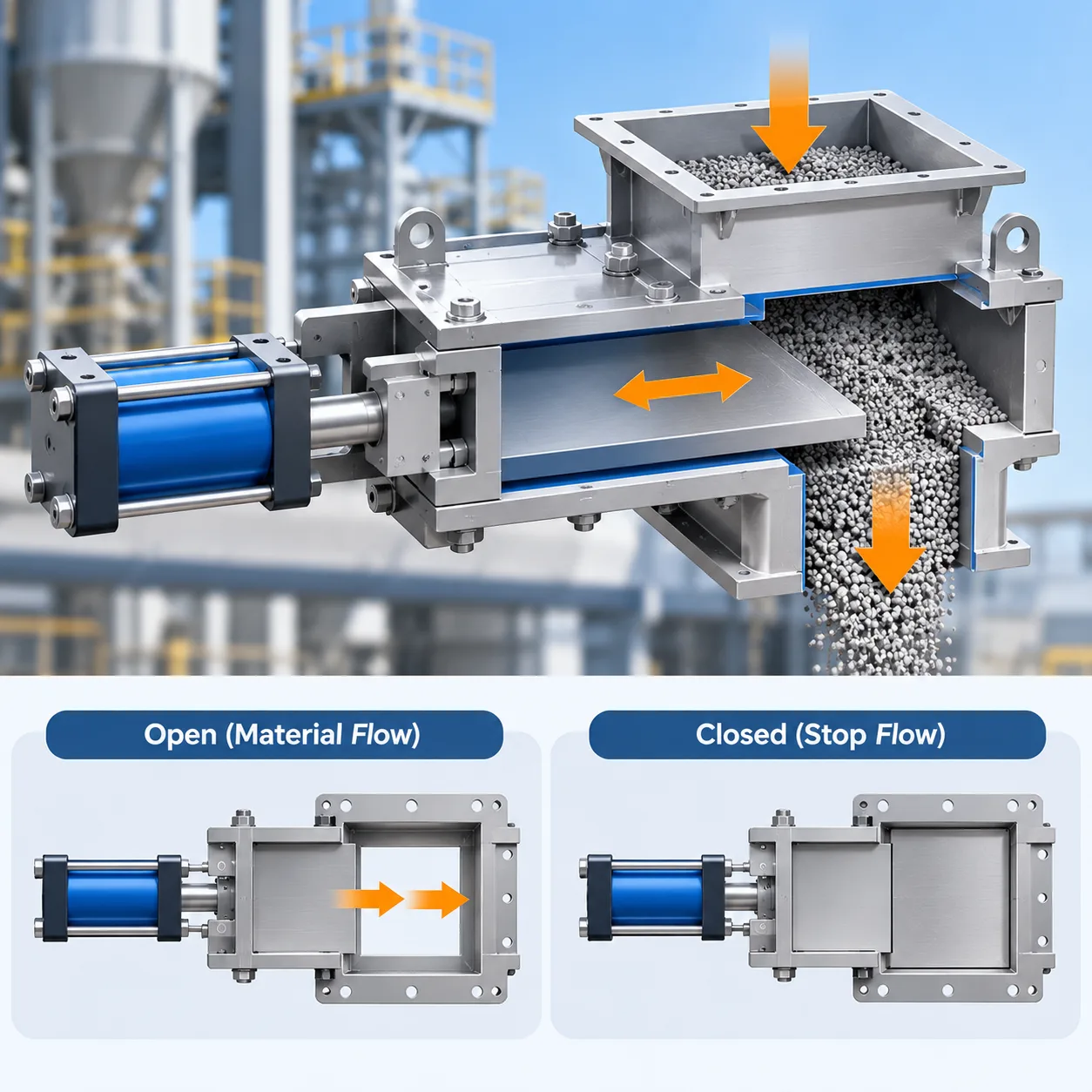
Quick Answer: How Does a Slide Gate Valve Work?
A slide gate valve operates on a straightforward linear motion principle: a flat plate or blade traverses perpendicular to a dry bulk material stream to start, stop, or meter gravity-fed product.
Core Operating Principle
The valve housing installs directly into discharge chutes, hopper outlets, or conveying lines. The working mechanism centers on a precision plate moving along guided tracks:
-
- Linear Blade Travel: Actuation thrust drives the flat blade horizontally through the active material column, cutting off the dry solids flow.
- Open Throat Clearance: In the fully open position, the blade retracts completely out of the throat, preventing bridging and maximizing throughput.
- Directional Force: The plate operates against static head load, relying on robust edge profiles to pass cleanly through powders, pellets, or granules.
Manual vs. Automated Movement Mechanisms
The method used to drive the blade defines everyday slide gate valve operation:
-
- Manual Actuation: Handwheels, chainwheels, or rack-and-pinion levers give operators dependable, mechanical control. We typically specify manual gates for low-frequency service, maintenance isolation, and emergency shutoffs where utility air or power is unavailable.
- Automated Actuation: Double-acting pneumatic cylinders or electric motor drives handle high-frequency cycling and remote automation. Pneumatic systems deliver rapid cutoff speeds within seconds, while electric screw jacks provide precise variable positioning for metered batching.
Factors Dictating Positive Shutoff and Sealing Performance
Achieving dependable shutoff in dry bulk handling requires balancing mechanical tolerances with product characteristics:
-
- Packing Gland Compression: Resilient perimeter seals and live-loaded packing prevent fine dust particles from migrating into the ambient plant environment.
- Blade and Seat Geometry: Hardened blade leading edges cleanly part the material column without wedging grains into the clearance tracks.
- Material Head Pressure: Heavy material columns exert downward force on the blade, making structural rigidity and low-friction linear guides critical to prevent binding during closure strokes.
What Is a Slide Gate Valve?
A slide gate valve is a mechanical valve designed specifically to isolate and regulate the flow of dry bulk solids. Unlike round pipe valves designed for water or gas, a slide gate uses a flat, rectangular or square sliding blade that moves directly across the material flow stream. We rely on them across processing facilities to start, stop, or throttle dry materials moving through gravity chutes, hopper outlets, and transfer points.
Understanding basic slide gate valve operation starts with looking at where and how they operate. These valves manage bulk material handling systems where conventional turning-disc or ball valves would instantly jam, wedge, or pack with dry particles.
Primary Functions in Bulk Solids Handling
We typically install slide gates in dry processing setups to handle two key jobs:
-
- Process Line Isolation: Providing reliable positive shutoff beneath storage silos, hoppers, and bins to shut off downstream equipment for maintenance or batch changes.
- Gravity Discharge Control: Regulating feed rates into mixers, bag dump stations, screw conveyors, and packaging lines by opening partially or cycling at controlled intervals.
Handled Materials
A properly specified slide gate handles a wide range of dry, non-liquid media without binding:
-
- Fine Powders: Cement, flour, starch, talc, fly ash, and carbon black.
- Pellets and Granules: Plastic resins, fertilizer prills, grains, and animal feed.
- Abrasive Solids: Sand, coal, mineral aggregates, and clinker.
Dry Bulk Slide Gates vs. Liquid Service Valves
You cannot drop a standard liquid valve into a bulk solids stream and expect it to work. While you can review specialized high-pressure fluid designs like parallel slide gate valve features and uses, dry bulk slide gates use completely different construction principles to handle solids without compacting them into dead zones.
| Feature | Dry Bulk Slide Gate Valve | Standard Liquid Service Valve |
|---|---|---|
| Flow Media | Powders, granules, bulk dry solids | Clean liquids, slurries, or gases |
| Obstruction Risk | Clear-throat aperture prevents material hang-up | Disc or ball creates flow pockets where powder packs |
| Blade Design | Flat plate traversing perpendicular to flow | Rotating disc, ball, or rising plug |
| Sealing Surface | Perimeter dust seals and displacement pockets | Resilient elastomer or metal-to-metal fluid seats |
| Wear Factors | Particle abrasion and static column load | Cavitation, erosion, and hydraulic pressure spikes |
Main Components of a Slide Gate Valve
Valve Body Housing and Flow Aperture
The outer housing forms the structural backbone of the unit. Fabricated from rigid carbon steel, cast iron, or stainless steel, it bolts directly between hoppers, chutes, or convey lines.
Aperture Profiles: Square, rectangular, or round flow paths match upstream discharge flanges to eliminate material hang-up.
Flange Alignment: Heavy-gauge structural walls prevent the frame from twisting under continuous pipe load or material head pressure.
Slide Plate (Gate) Construction
The slide plate, or blade, is the moving barrier that physically cuts off product flow.
Material Selection: Standard builds use heavy-gauge carbon steel or 304/316 stainless steel. For highly abrasive rock, clinker, or grains, we utilize hardened AR400 plate to resist gouging.
Edge Profiles: Leading edges are typically squared off for dry bulk solids or precision-beveled to slice through standing columns of dense powders without wedging.
Linear Guides, Rollers, and Blade Support Surfaces
Smooth travel relies entirely on how the blade is supported inside the body:
Hardened Rollers: Heavy-duty cam rollers support the plate from beneath, reducing travel friction under high static loads.
UHMW-PE Guide Rails: Low-friction polymer side guides keep the blade tracking dead-center, preventing metal-on-metal galling during rapid cycling.
Seals, Packing Glands, and Dust Wipers
Reliable containment keeps product inside the process line and off the plant floor:
Bonnet Packing Glands: Adjustable compression packing rings wrap around the rear blade path to prevent fine powders from migrating into ambient air.
Perimeter and Seat Seals: Resilient elastomer, silicone, or PTFE seals create firm perimeter contact when the valve fully seats.
Wiper Blades: Integrated scrapers strip caked material off the gate faces during retraction to protect downstream seal packages.
Actuation Mechanisms and Drive Linkages
The drive supplies the mechanical force needed to slide the gate through packed material. Depending on process demands, our industrial slide gate valves incorporate:
Pneumatic Cylinders: Fast, double-acting air cylinders for automated, high-cycle isolation.
Electric Screw Actuators: Precision-drive motor systems engineered for intermediate throttling and remote metering.
Manual Drives: Heavy-pitch ACME screws driven by handwheels or chainwheels for low-frequency service and maintenance shutoff.
Slide Gate Valve Operation: Step by Step
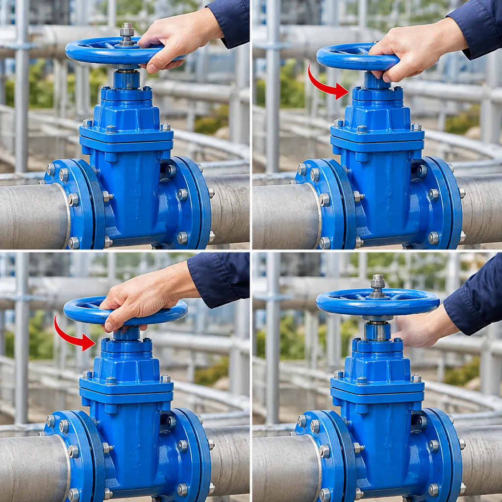
Step 1: Fully Closed Isolation Position
The cycle starts with the slide plate completely extended across the flow aperture. In this resting state, the blade rests firmly against the internal sealing package and end stop, supporting the static head load of standing material from the bin or hopper above. A tight seal prevents powders or granules from dribbling into downstream chutes.
Step 2: Actuation Command Initiated
When discharge is required, an operational signal triggers the drive mechanism:
Pneumatic systems supply pressurized air to shift a double-acting cylinder.
Electric setups energize an electric drive to turn a lead screw or rack-and-pinion.
Manual systems rely on an operator rotating a handwheel or pulling a chain wheel.
Step 3: Slide Plate Retracts to Open the Throat
As the actuator pulls, the blade slides back along internal support rollers or guide tracks. Once the blade clears the throat, gravity takes over and bulk material drops freely through the opening. High-quality guides keep the blade aligned during retraction so uneven head pressure does not cause the plate to bind.
Step 4: Plate Advances Through the Material Column
To stop discharge, the actuator reverses stroke and drives the slide plate forward. In active gravity systems, the leading edge must push directly through a falling or static column of dry bulk product. Sizing the actuator correctly is critical here: insufficient thrust will stall the blade halfway through the material stream, while a properly engineered heavy-duty slide gate valve provides enough shearing force to cut cleanly through the solids without deflecting.
Step 5: Full Stroke Completion and Seal Engagement
In the final fraction of travel, the blade drives fully into the recessed end seat:
Scraper seals and wipers sweep residual dust off the top and bottom blade surfaces to protect the packing gland.
Perimeter seals compress around the blade margins to isolate the line and prevent atmospheric dusting.
Limit switches confirm the gate has reached 100% closure, signaling the control room that downstream equipment can safely proceed to the next batch phase.
Mastering this five-step slide gate valve operation ensures smooth transitions between rapid dry bulk discharge and dependable process line shutoff.
Slide Gate Valve Actuation Methods
The drive mechanism powers the blade across the flow stream and dictates overall slide gate valve operation. Depending on whether you need simple maintenance isolation or automated throttling, we generally rely on three actuation setups.
Manual Operation: Handwheels, Chain Wheels, and Levers
Manual slide gate operation is the most straightforward, cost-effective method for low-frequency service:
-
- Handwheel and Lead Screw: Turning the handwheel rotates an Acme screw thread to smoothly push or pull the gate.
- Chain Wheels: Fitted onto overhead hoppers and silos, allowing ground-level operators to stroke the valve safely via an endless chain.
- Hand Levers: Best suited for small-aperture valves requiring immediate, quick manual shutoff.
- Best Used For: Maintenance isolation above equipment like rotary airlock valves, bin cleanouts, and non-routine process shutoffs.
Pneumatic Actuation: Double-Acting Air Cylinders
A pneumatic slide gate actuator uses plant compressed air (typically 60 to 90 PSI) to deliver fast, repeatable cycling:
-
- Double-Acting Cylinders: Air drives the piston in both directions for reliable opening and closing power.
- Cycle Speed: Strokes in seconds, cutting quickly through active material streams to stop flow immediately.
- Accessory Support: Readily accepts magnetic reed switches, solenoid valves, and air filter-regulators for full PLC automation.
- Best Used For: High-frequency batching, automated gravity load-out, and dusty or hazardous areas where electric motors pose safety risks.
Electric Actuation: Motor-Driven Positioning
When precision control matters more than raw speed, an electric slide gate actuator delivers controlled, motorized movement:
-
- Drive System: An electric motor paired with an industrial gearbox and screw jack or rack-and-pinion system.
- Remote Modulating: Equipped with variable positioners and 4–20 mA feedback signals to hold the blade partially open for metering material discharge rates.
- Mechanical Hold: Self-locking drive designs prevent the blade from drifting under static column pressure when power is off.
- Best Used For: Controlled material feeding, loss-in-weight batching systems, and outdoor installations lacking compressed air supply.
How to Select the Right Actuator
Matching the drive to your bulk material handling valve depends on four core jobsite conditions:
-
- Cycling Frequency: Use pneumatic drives for hourly or continuous cycling; use manual gearboxes for monthly or shutdown service.
- Available Utilities: If clean, dry compressed air is already piped to the deck, pneumatic cylinders provide the lowest operational cost.
- Position Control: If the application demands accurate throttling rather than a simple open/close stroke, select an electric motor drive.
- Fail-Safe Requirements: Pneumatic systems can integrate air storage tanks or mechanical springs to automatically close the gate during a sudden plant power loss.
Common Industrial Applications for Slide Gate Valves
In dry bulk processing, we deploy these units wherever gravity discharge or differential pressure requires positive material shutoff. Understanding how does a slide gate valve work across varying process conditions helps determine the right blade profile, seal choice, and drive configuration.
Here are the primary field installations where dependable slide gate valve operation is essential:
-
- Gravity Discharge from Bins, Silos, and Hoppers: Bolting a heavy-duty slide gate directly to the discharge cone of large storage vessels—such as bulk cement silos—allows operators to isolate downstream equipment from extreme static head loads during maintenance or batching cycles.
- Conveyor Discharge Points and Chute Diverters: Positioned along belt conveyors, drag chains, or screw feeders, these gates act as intermediate discharge stations, dropping powders or aggregates into specific process lines on demand.
- Pneumatic Conveying Feed and Isolation Points: Mounted above rotary airlocks or venturi boots, the gate isolates vacuum or dilute-phase pressure lines, stopping air bypass and preventing fine powders from flooding the conveying stream.
- Dust Collection Hoppers and Baghouse Outlets: Underneath industrial baghouse dust collectors, an airtight gate prevents system pressure loss while periodically emptying captured fines into barrels, roll-off boxes, or disposal conveyors.
Key Factors That Affect Slide Gate Valve Performance
Understanding how a slide gate valve works in real-world plant conditions means looking beyond the bench test. In our experience across diverse processing facilities, predictable slide gate valve operation depends heavily on the interface between the dry bulk material, the mounting structure, and the operating environment.
Bulk Material Characteristics
The physical nature of the handled media directly influences blade wear, actuation resistance, and seal integrity:
Abrasiveness: Highly abrasive materials like clinker, sand, or mineral ores accelerate edge wear on standard carbon steel plates, demanding hardened tool steel or abrasion-resistant liners.
Moisture Content: Sticky or hygroscopic powders tend to pack into guide channels and internal corners, creating material buildup that stalls the drive.
Cohesion and Particle Size: Fine powders can aerate and fluidize, testing blade perimeter seals, while irregular large aggregates risk jamming between the advancing blade and the valve seat.
Material Head Load and Static Column Pressure
When installed beneath deep silos or storage bins, the valve blade bears the full weight of the resting material column. This static head pressure generates significant friction along the horizontal slide rails. If the actuator lacks sufficient breakaway force to overcome this load, the blade can bind mid-stroke, disrupting steady bulk solids flow control.
Installation Geometry and Structural Flange Alignment
A slide gate valve housing must remain completely flat to ensure smooth travel:
Bolting a valve to an uneven, warped hopper flange twists the frame.
Frame distortion pinches internal rollers and guides, preventing the slide plate from completing its stroke.
Always verify flange flatness and use rigid mounting transitions before torquing hardware.
Dust Containment Demands vs. Shutoff Standards
Dry bulk slide gates are primarily designed for positive mechanical shutoff of solids rather than bubble-tight gas containment. However, fugitive dust creates safety hazards and product loss. Achieving proper dust containment requires selecting appropriate packing glands and displacement seals, especially when feeding dust-sensitive downstream systems like truck loading spouts where clean material transfer is critical.
Cycle Frequency and Ambient Environmental Conditions
Operating conditions dictate the mechanical wear curve of your valve assembly:
Duty Cycle: High-cycle valves actuating several times a minute need continuous-duty pneumatic cylinders or robust mechanical linkages, whereas low-frequency maintenance gates focus primarily on seat corrosion resistance.
Thermal Expansion: Elevated process temperatures cause the blade to expand faster than the ambient housing, requiring engineered expansion clearances to prevent blade seizure during operation.
Ambient Exposure: Outdoor installations require weather-protected actuators, corrosion-resistant hardware, and sealed switches to withstand moisture, freezing temperatures, and plant washdowns.
Troubleshooting Common Slide Gate Valve Problems
When a slide gate valve fails in the field, it usually halts the entire process line. Understanding how does a slide gate valve work under harsh conditions makes diagnosing operational faults straightforward. We regularly encounter four core issues on plant floors:
Gate Binding or Failing to Stroke Smoothly
A blade that sticks or jerks during slide gate valve operation usually points to internal mechanical interference:
Material buildup: Fine powders pack tightly into the lateral guide tracks and blade slots, wedging the plate in place.
Guide rail misalignment: Over-torqued flange bolts or structural deflection can warp the housing, pinching the blade between internal supports.
Foreign object obstruction: Tramp metal or oversized aggregates lodged between the blade edge and the seat prevent travel.
Material Leaking Past the Closed Gate Blade
Dry bulk slide gates are designed for positive mechanical shutoff, not bubble-tight gas seals. However, persistent product blow-by indicates component wear:
Seat wear or erosion: Abrasive materials erode the bottom landing bar and perimeter seals over high cycle volumes.
Blade deflection: Heavy static material head loads can bow a thin gate blade, creating gaps along the sealing perimeter.
Incomplete closure: Compacted product in the rear seal cavity stops the blade before it fully mates with the leading-edge seal.
Dust Escaping Through Bonnet Seals and Packing Glands
Fugitive dust around the actuator mounts or bonnet indicates failure in the dust-retention assembly. We see this frequently when handling pressurized fines without proper venting, especially upstream of a cement plant dust collection system.
Compacted or degraded packing: Braided Teflon, PTFE, or felt wipers dry out, wear thin, or crack over time.
Positive line pressure: Excessive backpressure forces fine particles through the packing glands during blade travel.
Scored blade surface: Deep scratches on the slide plate drag dust through the gland seals on every stroke.
Actuator Stall or Incomplete Stroke Cycles
When the drive unit fails to position the blade, check both the power source and the mechanical resistance:
Low pneumatic supply pressure: Air cylinders require steady pressure to shear through standing columns of bulk material. Verify supply lines and regulator settings.
Faulty limit switches: Misaligned proximity sensors signal the control system that the valve has completed its cycle when the blade is only partially closed.
Binding drive linkages: Pinched cylinder clevises, worn electric jack screws, or stripped drive chains prevent the motor from transferring full thrust to the gate blade.
Essential Slide Gate Valve Maintenance Practices
Dry bulk handling takes a toll on moving parts, and skipping basic upkeep directly impairs slide gate valve operation, leading to jammed blades and costly process downtime upstream of key bulk conveying equipment.
Routine Inspection Intervals
We set up inspection schedules based on cycle frequency and material type. High-cycle gates handling abrasive powders need weekly visual checks, while low-frequency emergency shutoff valves can run on monthly or quarterly schedules.
During every round, we look for:
Blade travel speed: Hesitation or jerky motion usually signals binding along the track.
Actuator linkage play: Loose clevis pins or misaligned cylinder rods create off-center side loads.
Material buildup: Dust pooling on external framing or packing glands points to internal seal breakdown.
Clearing Guide Rails and Seats
Material accumulation is the number one cause of valve failure. When fine powders pack into the lateral guides or rear blade housing, the drive motor or cylinder stalls out before the blade fully closes.
Blow out internal tracks: Use dry compressed air to clear settled dust around rollers and slide rails during downshifts.
Scrape the seat perimeter: Remove caked or compacted material along the downstream landing zone so the leading edge can close completely.
Flush wiper cavities: Check that dust-retention scrapers are actively clearing product off the blade surface with every stroke rather than dragging debris into the bonnet.
Replacing Seals and Wear Liners
No seal lasts forever in dry bulk environments. Once product dust migrates past the blade, friction skyrockets and ruins the surrounding hardware.
Packing gland seals: Tighten the packing bolts evenly to stop minor dusting. If the packing is hard, glazed, or deeply grooved, pull it and repack it.
Perimeter and bonnet seals: Replace worn polymer or felt seals whenever you see dust leaking around the actuator mount or valve housing.
Abrasion-resistant wear liners: Inspect the internal bore liners. Replacing a worn drop-in liner takes minutes and prevents the main valve frame from eroding under high-velocity dry solids.
Safety Protocols: LOTO and Stored Energy
A slide gate blade acts as a guillotine. Never touch the flow path or internal rails without completing full safety isolation:
Lockout/Tagout (LOTO): Lock out electrical supplies to motor drives and shut off supply lines to pneumatic or hydraulic actuators.
Zero-pressure verification: Vent air cylinders and drain line accumulators completely. Trapped air pockets can shift the blade even after the main compressor supply is locked out.
Mechanical blade blocking: Insert physical safety pins or wooden blocks into the gate frame before inspecting the throat to eliminate any risk of accidental travel.
Slide Gate Valve vs. Knife Gate Valve
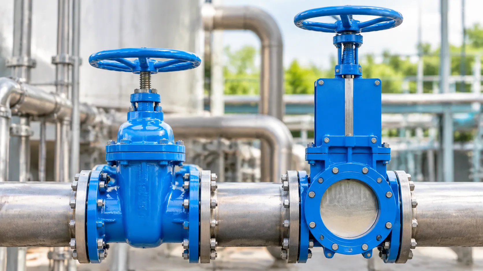
We often see plants confuse a slide gate with a knife gate. While both use a linear blade to halt flow, their internal mechanics and intended media are fundamentally different.
Design Differences: Flat Plate vs. Beveled Edge
-
- Slide Gate Valves: Feature a flat, uniform plate supported by internal rollers or low-friction side guides. In standard slide gate valve operation, the plate pushes horizontally through gravity-fed dry solids to seal against perimeter gaskets and dust seals without relying on fluid pressure.
- Knife Gate Valves: Utilize a blade with a sharp, beveled edge. The knife gate working principle relies on that tapered edge to slice through thick masses, stringy solids, and viscous fluids, wedging the blade directly into a resilient bottom seat.
Media Handling: Dry Bulk Solids vs. Slurries
| Operational Parameter | Slide Gate Valve | Knife Gate Valve |
|---|---|---|
| Primary Media | Dry powders, pellets, granules, bulk solids | Slurries, pulp, wastewater, viscous liquids |
| Blade Geometry | Flat, durable steel plate | Beveled, sharpened cutting blade |
| Flow Orientation | Vertical gravity discharge or chutes | Horizontal/vertical pressurized piping |
| Sealing Surface | Dust-tight packing glands and side guides | Resilient elastomeric or metal seat |
| Jamming Prevention | Deflector cones, blade wipers, throat clearance | Direct shearing through flow stream |
When to Specify a Slide Gate Valve
Choose a dedicated bulk material handling valve like a slide gate when handling dry materials under gravity or low-pressure feed. We recommend specifying a slide gate for:
-
- Silo and Hopper Outlets: Isolating free-flowing powders, pellets, and bulk materials above processing units.
- Conveyor Feeds: Regulating or shutting off dry feed into continuous screw conveyors and weigh hoppers.
- Dust Containment: Trapping fugitive dust in dry lines where liquid-style knife gates would allow particles to pack into the bottom seat and prevent full closure.
If your process line contains liquid carriers, heavy chemical slurries, or paper pulp, choose a knife gate valve. For dry bulk handling where unobstructed flow and zero seat packing are required, a slide gate valve is the correct choice.
How to Select the Right Slide Gate Valve
Selecting the right valve comes down to matching your bulk material properties with your line's mechanical demands. Here is how we evaluate each parameter to ensure reliable slide gate valve operation:
1. Assess Material Flowability and Temperature
-
- Flow characteristics: Fine, aerated powders require tight internal clearances and blade wipers to prevent dust migration. Sticky or hygroscopic materials need non-stick blade coatings or self-cleaning deflection cones.
- Operating temperature: Standard seals and polymer guides work well below 180°F (82°C). High-heat processes require high-temperature packing gland materials, silicone seals, and extended actuator mounts to isolate heat.
2. Match Throat Dimensions and Flange Patterns
-
- Aperture size: The throat dimension must match or exceed your hopper or silo outlet. Restricting the opening creates ledges that encourage material bridging.
- Shape and drilling: Match your existing ductwork geometry (round vs. square/rectangular) and confirm flange bolt patterns to eliminate field modifications. Review our engineering bulk handling resources when planning transition chute interfaces.
3. Define the Operational Duty Cycle
-
- Emergency or Maintenance Shutoff: Simple open/close duty with low cycle frequency favors straightforward manual or standard pneumatic setups.
- Flow Metering or Throttling: If you need to meter dry bulk discharge, choose an electric actuator with positioning feedback or a pneumatic cylinder equipped with intermediate stops. Understanding how a slide gate valve works under partial-stroke conditions ensures the blade can handle dynamic material drag without deflecting.
4. Choose Construction Materials
Your product contact surfaces must withstand chemical attack, washdown moisture, and abrasive wear.
| Material Option | Best Application | Key Advantage |
|---|---|---|
| Carbon Steel | Non-corrosive, non-food dry grains, pellets, and standard minerals | Economical and structurally rigid under high head loads |
| 304 / 316 Stainless Steel | Food processing, pharmaceuticals, chemical handling, washdown zones | Corrosion resistance and sanitary product protection |
| AR (Abrasion-Resistant) Plate | Crushed stone, clinker, fly ash, and abrasive aggregates | Extended blade life against continuous surface scouring |
| Hard Chrome / Hardfacing | High-velocity fine particles and aggressive sliding wear | Reduces friction and prevents blade galling under static pressure |
Matching these specifications upfront ensures seamless integration into your dry bulk industrial equipment products while keeping routine maintenance to an absolute minimum.
Frequently Asked Questions About Slide Gate Valves
Can a slide gate valve be used for precise flow metering?
Standard units work primarily for on/off isolation, but we frequently configure them for batching and variable discharge. To achieve dependable slide gate valve flow control, we mount variable positioners, modulating electric drives, or multi-position pneumatic cylinders. This lets the blade halt at preset intervals across the throat. While highly effective for free-flowing pellets and dry grains, fine powders can aerate and flood past partial openings, making rotary valves or feeder screws a better match for micro-dosing.
Can slide gate valves handle moist or sticky materials?
Moist, cohesive, or hygroscopic solids present operational hurdles. Wet bulk products tend to smear across the plate, compact into the side guides, and pack solidly into the end gate cavity. If you must run sticky bulk materials, we recommend:
Curved or beveled blades that slice rather than plow.
Non-stick polymer liners or specialized blade coatings.
Self-cleaning deflector pockets to shed cake buildup before the gate closes into the frame.
What is the primary cause of a slide gate valve jamming?
Material packing in the blade guides and end-seal seal pocket causes the vast majority of gate stalls. When you examine how does a slide gate valve work under continuous plant operation, the leading edge pushes standing product directly into the back-stop during each closing stroke. If the clearances are wrong or fine dust bypasses the seals, friction builds up quickly. Excessive material head pressure on an under-designed, deflecting blade will also wedge the gate tight against its rollers.
How do pneumatic slide gates handle power or air loss?
A standard double-acting pneumatic slide gate valve generally holds its last position during a sudden air loss because line pressure equalizes on both sides of the piston. When process safety mandates an automatic fail-safe state, we integrate:
Mechanical spring-return cylinders to pull the blade immediately open or push it closed.
Dedicated pneumatic reserve tanks equipped with check valves to provide enough stored air volume for a final emergency stroke.
Fail-safe spring solenoids that route reserve pressure directly to the designated safety port during power trips.
How long do slide gate seals typically last in bulk solids handling?
Seal lifespan ranges from six months to several years depending directly on your product's abrasiveness, system cycling rates, and operating temperatures. When installed beneath hoppers on systems like pulse-jet dust collectors, fine fugitive dust puts constant friction on perimeter packing glands. Routine inspection intervals and adjustable seal retainers allow you to tighten packing on the fly, compensating for natural wear without pulling the entire assembly out of the process line.