What Is a Parallel Slide Gate Valve?
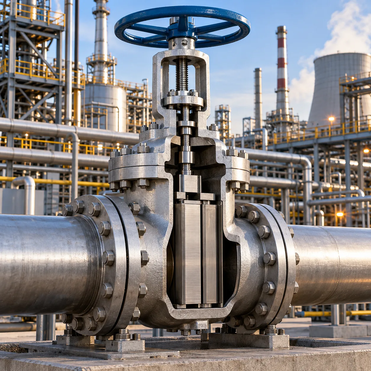
A parallel slide gate valve is a linear-motion isolation valve designed to stop or allow fluid flow using two parallel sliding discs instead of a tapered wedge. When asking what is parallel slide gate valve technology at its core, the answer lies in its pressure-energized design: the valve relies on line media pressure—supported by an internal spring assembly—to push the downstream disc firmly against the seat ring for a tight, reliable seal.
Core Design Concept
Unlike traditional valves that jam a closing member into a tapered pocket, our parallel slide gate valves use flat, parallel seating faces:
-
- Dual Parallel Discs: Two independent discs slide smoothly across parallel seat rings during cycling.
- Internal Spring Loading: A central spring keeps both discs in continuous contact with the seats at low differential pressures, preventing particulate buildup and seat damage through a continuous wiping action.
- Pressure-Assisted Sealing: As line pressure rises, the upstream media forces the downstream disc tightly onto its seat, creating a dependable, bi-directional isolation barrier.
How It Differs from Wedge Gate Valves
The fundamental distinction between a parallel slide gate valve and a wedge gate valve comes down to mechanical wedging versus pressure containment:
-
- Thermal Binding Resistance: Wedge valves drive a tapered gate between angled seats. Under high thermal expansion, the wedge often binds or jams inside the body neck. Parallel slide gate valves eliminate thermal binding because the discs expand freely along the parallel seat plane without locking.
- Operating Torque: Opening a standard wedge valve requires substantial breakout torque to unseat the wedged component. Parallel slide designs require lower operating torque since movement only involves overcoming sliding friction under system pressure.
- Seat Wear and Longevity: The wiping motion of parallel discs clears scale and pipeline debris across every stroke, whereas wedge seating impacts the body directly, increasing the risk of scoring and premature seat failure.
How Parallel Slide Gate Valves Work
Understanding what is a parallel slide gate valve during active operation comes down to two key factors: linear disc travel and fluid-assisted sealing. Unlike wedge-type designs that rely on mechanical force to jam a gate into a tapered body, our parallel slide valves use line pressure to achieve a bubble-tight seal without mechanical stress.
The Operating Mechanism
The disc assembly travels vertically across the flow path on parallel seat faces. When cycling the valve:
-
- Opening: The stem pulls the disc assembly up into the bonnet, clearing the bore completely for an unobstructed, full-bore flow path.
- Closing: The stem drives the two parallel discs down between the seats. A continuous wiping action across the seat faces cleans off debris, scale, and particulate matter during every cycle.
- Friction reduction: Because the discs slide across flat, parallel faces rather than wedging tightly into place, stem operating torque stays low across all pressure ranges.
For a detailed visual breakdown of disc movement, explore our parallel slide gate valve operation guide.
The Role of Line Pressure and Spring Loading
A dependable spring-loaded gate valve design relies on internal springs positioned between the two discs. These springs do not provide the ultimate sealing force; instead, they serve a specific mechanical role:
-
- Low-pressure initial contact: Under zero or low system differential pressure, the internal springs push both discs lightly against their respective seat faces to prevent bypass.
- Fluid pressure engagement: As system pressure builds, the upstream fluid enters the valve body and forces the downstream disc hard against the downstream seat.
- Self-adjusting seal: Higher line pressure results in a tighter seal against the downstream face, eliminating the need for excessive torque on the handwheel or actuator.
Sealing Principle: Upstream vs. Downstream Sealing
The sealing mechanics of this design function through a distinct upstream-to-downstream relationship:
-
- Downstream Seating: The actual fluid shut-off happens almost entirely on the downstream seat. Medium pressure acts across the back of the disc assembly, pushing the downstream disc directly onto its seat ring.
- Upstream Relief: The upstream disc floats slightly away from its seat as line pressure enters the body cavity. This equalizes pressure across the upstream side and prevents high-pressure fluid from getting trapped inside the bonnet, fully avoiding the risk of thermal binding or pressure-lock failures.
Key Components and Materials of Parallel Slide Gate Valves
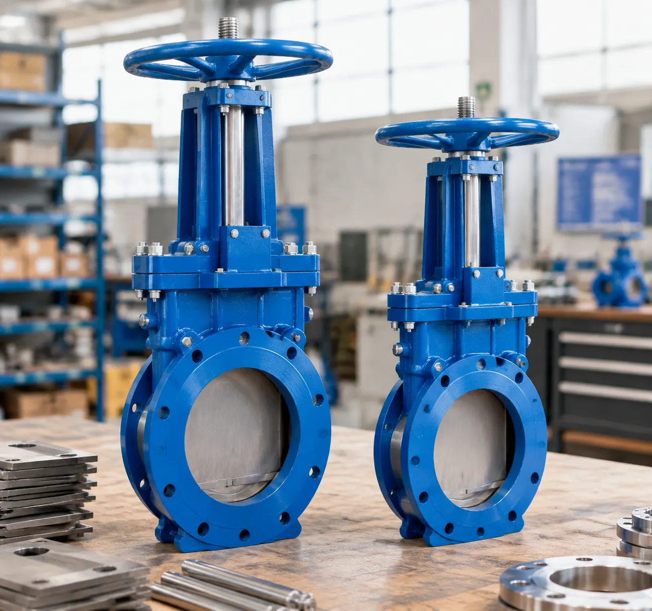
To understand what a parallel slide gate valve is from an engineering perspective, we need to break down its internal anatomy. The valve relies on a clean, low-stress internal assembly that withstands extreme thermal cycles and severe mechanical loads.
Valve Body and Bonnet Configuration
The outer pressure boundary houses the internal flow path and isolates the medium from the surrounding atmosphere.
Body Construction: Typically cast or forged from heavy-duty carbon steel, alloy steel, or stainless steel to manage severe steam and high-pressure duties.
Bonnet Joints: Standard applications use a bolted bonnet design for straightforward maintenance, while critical high-pressure, high-temperature lines utilize a pressure seal bonnet that uses the system line pressure to tighten the seal further. Explore our broader range of heavy-duty valves and flow control equipment to see how these body configurations match specific plant setups.
Discs and Pressure Springs
Instead of a single solid wedge, the parallel slide valve disc assembly uses twin parallel discs separated by a internal spring mechanism.
Dual Discs: Two independent flat plates slide across matching parallel seats. They do not jam together mechanically, which prevents thermal binding entirely.
Central Spring: A stainless steel or high-nickel alloy spring sits between both discs. It delivers constant outward mechanical force, holding the discs tight against the seats at low differential pressures and continuously wiping away line scale.
Stem Types: Rising vs. Non-Rising
The stem transfers manual or automated actuator torque directly into the linear movement of the disc carrier.
Rising Stem (Outside Screw and Yoke - OS&Y): The stem lifts externally as the valve opens. This design isolates the stem threads from hot or corrosive fluids and provides an instant visual indicator of valve position.
Non-Rising Stem: The stem threads stay inside the body while the disc travels along the shaft. This configuration saves vertical clearance in tight piping layouts where overhead space is restricted.
Benefits of Using Parallel Slide Gate Valves
When evaluating what is a parallel slide gate valve advantage in real-world systems, the benefits come down to reliability under heavy stress.
Prevention of Thermal Binding
In extreme steam and hot fluid lines, metal naturally expands. Conventional wedge gates often jam shut when high temperatures cause the wedge to expand tightly into the tapered body seats—a failure mode known as thermal binding. A parallel slide gate valve utilizes two independent parallel discs that slide across parallel seats. Because there is no mechanical wedging action, the discs expand freely without locking into the seat pocket, ensuring smooth opening and closing every single cycle.
Reduced Operating Torque Requirements
Unlike wedge valves that require heavy mechanical force wedged into the seat to seal, parallel slide units rely on the system line pressure to push the downstream disc firmly against the seat ring.
Smaller Actuators: Lower operational torque means you can use smaller, cost-effective electric or pneumatic actuators.
Effortless Manual Cycling: Operators can cycle valves manually with far less physical strain, even under high differential pressures.
Extended Service Life in High-Temperature Applications
High-velocity steam and hot media carry particulates that quickly damage stationary sealing faces. As a dedicated China slide gate valve manufacturer, our disc assemblies are engineered to maintain continuous contact with the seats during travel. This sliding travel creates a self-cleaning wiping action that cleans off scale and debris, reducing galling and extending seat life. For severe pipeline runs, deploying a big size slide gate valve for industrial flow control ensures consistent isolation without premature maintenance overhauls.
| Key Benefit | Parallel Slide Gate Valve | Standard Wedge Gate Valve |
|---|---|---|
| Thermal Binding Risk | Zero (parallel sliding discs absorb thermal growth) | High (wedge jams due to body contraction/disc expansion) |
| Operating Torque | Low (pressure-energized sealing, no mechanical wedging) | High (requires high seating/unseating torque) |
| Seat Face Wear | Minimal (wiping action cleans debris across seat faces) | Moderate to High (friction and point-loading during seating) |
| High-Temp Steam Stability | Superior (consistent tight shut-off across cycles) | Limited (prone to leakage after cooling/heating cycles) |
Common Industrial Applications for Parallel Slide Gate Valves
I have found that the design of the parallel slide gate valve makes it a top-tier choice for demanding environments where reliability is non-negotiable. Because these valves handle high pressure and temperature shifts so effectively, they are staples in several key sectors:
-
- Power Generation and Steam Systems: These valves are frequently used as steam isolation valves in power plants. Their ability to handle high-velocity steam without the risk of thermal binding ensures that critical boiler feed lines and main steam headers remain operational and secure.
- High-Pressure Fluid Management: When dealing with intense pressure, the bi-directional sealing mechanism provides the stability required for complex piping networks. Whether managing water or other industrial fluids, these valves prevent leaks even under severe load, which is critical for maintaining equipment resources.
- Chemical Processing Plants: In environments involving corrosive or high-temperature media, the robust construction of a parallel slide gate valve offers a durable solution. Engineers prefer them in chemical refining, where consistent seat alignment and longevity are vital to reducing maintenance cycles.
By integrating these valves into your high-pressure fluid management systems, you ensure long-term performance and minimize the risk of mechanical failure in your most sensitive industrial circuits.
Parallel Slide Gate Valve Maintenance and Troubleshooting Tips
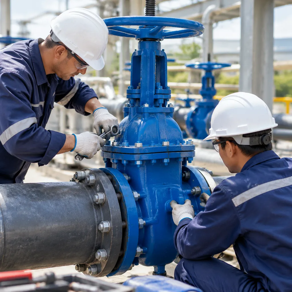
Understanding what is a parallel slide gate valve involves knowing how to service its unique internal components. Because these units rely on system pressure and spring tension rather than mechanical wedging, routine servicing focuses on disc mobility, seat integrity, and stem operation.
Routine Inspection Procedures
To keep these industrial gate valves performing reliably in high-pressure lines, we follow a straightforward inspection schedule:
-
- Stem Packing and Gland Checks: Inspect the stuffing box for any signs of media leakage. Tighten gland bolts evenly to prevent stem binding.
- Cycle Testing: Periodically stroke the valve fully open and fully closed. This clears minor particulate buildup and confirms that the rising stem travels smoothly without excessive operating torque.
- External Housing Inspection: Check the bonnet joint and pressure seal area for signs of weepage or corrosion under working pressure.
How to Identify Seat Leakage
A damaged slide gate valve seat design or a compromised valve disc assembly will immediately show up in downstream monitoring. Here is how we diagnose internal bypass:
-
- Downstream Pressure and Temperature Tracking: In steam isolation valves, a persistent downstream temperature rise after full closure indicates that fluid is bypassing the parallel faces.
- Acoustic and Ultrasonic Detection: Handheld acoustic leak detectors easily detect the high-frequency hissing of pressurized fluid slipping between the sliding discs and seats.
- Low-Pressure Sealing Loss: If the valve seals under heavy line pressure but leaks during low-pressure startup, inspect the internal disc springs. Weak or broken springs fail to provide the initial mechanical load necessary for low-differential shut-off.
Cleaning and Lubrication Best Practices
Proper lubrication and cleaning prevent premature wear on seating faces and actuator interfaces:
-
- Lubricate Stem Threads: Apply high-temperature, anti-seize grease to the external stem threads and yoke bushing regularly. Never allow the stem to run dry.
- Flushing the Valve Cavity: Before closing the discs in dirty media lines, flush the pipeline if possible. While the sliding action wipes the seat faces naturally, large particulates can cause galling across the parallel seats.
- Evaluate Valve Selection During Overhauls: When servicing fluid handling systems, compare operational demands across your facility. While parallel slide units excel in high-pressure thermal service, quarter-turn alternatives like industrial butterfly valves may be better suited for low-pressure, rapid-cycling lines. For deeper maintenance breakdowns across various valve configurations, explore our engineering resources blog.
Parallel Slide Gate Valve vs. Wedge Gate Valve
A parallel slide gate valve utilizes two flat discs that move parallel to each other, while a traditional wedge gate valve relies on a tapered disc that forces itself into the seats.
Choosing the right design often comes down to your specific service environment, particularly regarding thermal conditions and pressure demands.
Comparison Table: Parallel Slide vs. Wedge Gate
| Feature | Parallel Slide Gate Valve | Wedge Gate Valve |
|---|---|---|
| Sealing Mechanism | Pressure-assisted, parallel faces | Mechanical wedging action |
| Thermal Binding | Highly resistant | Prone to jamming |
| Operating Torque | Lower; no wedging force needed | Higher; friction from wedging |
| Primary Use | High-temperature steam | General isolation |
| Seat Wear | Minimal (wiping action) | Higher (friction contact) |
When to Choose Which Type
-
- Choose Parallel Slide Gate Valves for: High-pressure steam systems where temperature fluctuations are common. Because these valves do not rely on mechanical wedging, they prevent the "thermal binding" often seen in wedge valves when cooling or heating cycles occur. They are ideal for applications requiring consistent performance under extreme heat.
- Choose Wedge Gate Valves for: Standard, lower-temperature applications where a tight shut-off is required without the complexity of a spring-loaded assembly. They are effective for general-purpose fluid management where the cost-to-performance ratio for routine maintenance is the primary concern.
Selecting the parallel slide design ensures that you minimize seat wear and avoid the mechanical stresses associated with forcing a wedge into a constrained space, leading to more predictable performance in demanding industrial environments.
Frequently Asked Questions (FAQs)
Why does the parallel slide gate valve perform better in high-heat scenarios?
In extreme steam and thermal cycles, conventional wedge gates frequently suffer from thermal binding. When temperatures spike, a tapered wedge expands directly into the valve body seats, jamming the valve shut and making it impossible to reopen without extreme torque.
When clients ask us what is a parallel slide gate valve advantage in steam headers, we point straight to the geometry:
Freedom of expansion: The parallel disc design relies on flat, parallel faces rather than an angled wedge.
Zero mechanical wedging: As thermal expansion occurs, the discs simply glide along the seat faces without getting pinched or locked into a pocket.
Consistent operation: Actuators and handwheels operate under stable torque requirements even during abrupt temperature swings.
Can these valves be used for throttling applications?
No, you should never use a parallel slide gate valve for throttling. These units are built strictly for full-open or full-closed isolation.
If you leave the valve partly open:
High-velocity fluid rushes across a narrow opening, causing severe wire-drawing and erosion across the seat faces.
Fluid turbulence causes unsupported discs to flutter and chatter against the seats.
Vibration can fatigue internal springs and destroy precision-lapped sealing boundaries within days.
For modulating flow, always pair your isolation units with dedicated globe or control valves from our broader lineup of industrial equipment and flow products.
How do you handle maintenance of the spring-loaded discs?
Servicing the internal disc assembly requires standard inspection protocols during scheduled outages. When servicing spring-loaded parallel slide discs, we focus on three primary checks:
-
- Spring tension and condition: Inspect the internal springs for corrosion, thermal fatigue, or cracking. Springs must maintain enough initial tension to hold the discs against the seats when line pressure drops to zero.
- Disc-to-seat flatness: Check the lapped sealing surfaces for scoring, scale buildup, or uneven wear patterns. Minor scratches can often be relapped in place.
- Free travel and clearance: Ensure the disc carrier allows the discs to float freely. Any scale, particulate buildup, or debris between the discs must be cleared away so both plates adjust independently to line pressure.