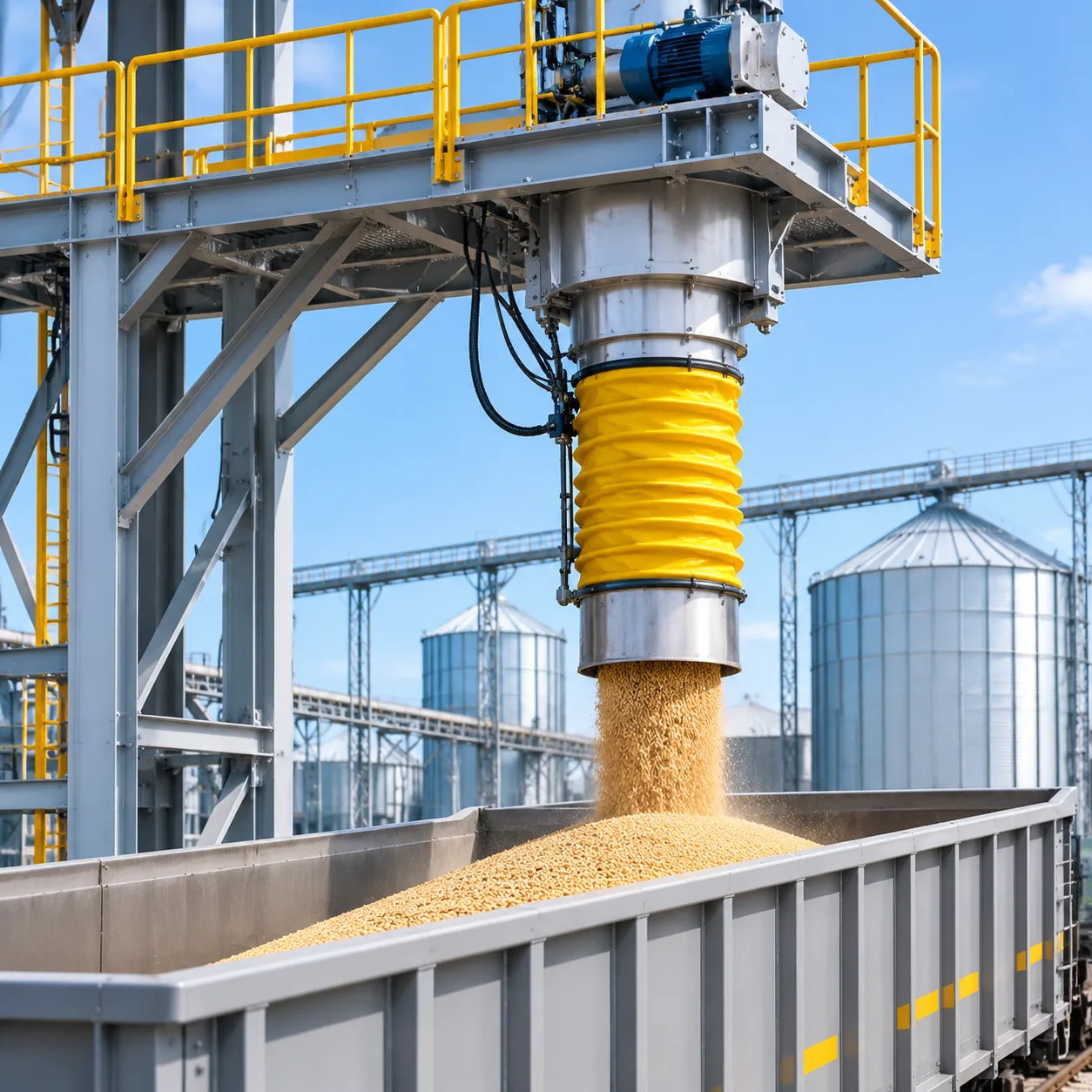

Formula details
Product Details
Overview
What Is a Big Size Slide Gate Valve?
A big size slide gate valve is a heavy-duty industrial valve designed to shut off, meter, or isolate dry bulk materials across large-aperture hopper bottoms, storage silos, and discharge chutes. Typically engineered in dimensions starting from 600 mm (24 inches) up to 2,500 mm (100 inches) and beyond, these units handle high-volume gravity flows of powders, granular products, and abrasive aggregates.
Core Mechanics of Sliding Plate Shutoff
The operating principle relies on a precision-machined, flat or chamfered steel blade traveling horizontally across the material flow path:
-
- Positive Blade Travel: The gate plate slides perpendicularly between high-density perimeter seals and hardened lateral guides, cutting through standing columns of static or moving bulk solids.
- Zero In-Stream Obstruction: When fully retracted, the valve provides an unrestricted, full-bore opening that eliminates flow resistance and reduces material bridging.
- Self-Cleaning Edge Design: The leading edge of the blade incorporates a beveled or knife profile that slices through packed solids and pushes residual dust out of the sealing pocket upon full closure.
Standard vs. Big Size Slide Gate Valve: Key Structural Differences
Scaling up gate dimensions multiplies the mechanical loads exerted by bulk head pressure. A slide gate valve in big size requires distinct structural upgrades compared to standard, smaller-footprint units:
| Feature | Standard Slide Gate Valve (≤ 500 mm / 20") | Big Size Slide Gate Valve (≥ 600 mm up to 2500 mm) |
|---|---|---|
| Blade Thickness | 6 mm – 10 mm standard plate | 16 mm – 35+ mm reinforced plate with deflection ribbing |
| Frame Construction | Formed sheet metal or light structural channels | Heavy structural steel with external gussets and stiffeners |
| Blade Support | Low-friction polymer slide rails | Hardened steel rollers, cam followers, and heavy guides |
| Drive Mechanisms | Standard pneumatic cylinders or manual wheels | Oversized dual cylinders, hydraulic drives, or electric jacks |
| Material Load Capacity | Light to medium bulk densities (< 800 kg/m³) | High bulk densities (> 2,000 kg/m³) and severe head loads |
Gravity Flow Isolation vs. Continuous Discharge Regulation
Depending on process requirements, we configure large-diameter slide gates for two primary operating modes:
-
- Positive Gravity Flow Isolation (On/Off): Functions as a critical safety and maintenance gate directly below silos and hoppers. It seals against deep material heads, isolating downstream equipment like rotary airlocks, screw conveyors, and weigh scales for zero downstream leakage during maintenance.
- Continuous Discharge Regulation (Metering): Utilizes variable positioning actuators paired with V-port or modified rectangular blade profiles. This allows plant operators to throttle material discharge, control feed rates to process lines, and maintain uniform bin drawdown without risking bridging or sudden material flushing.
Key Features of Our Heavy-Duty Big Size Slide Gate Valves
Handling high-tonnage dry bulk solids requires equipment that can withstand immense head loads without mechanical binding. When a standard gate is scaled up, ordinary flat plates bow under thousands of pounds of standing material pressure, leading to actuator stall, seal blowouts, and severe fugitive dusting.
Explore our full industrial line of slide gate valves engineered for dependable isolation under severe bin-discharge conditions.
Reinforced Body Design Against Deflection
-
- Heavy Structural Channel Framing: We build each valve body using welded structural carbon steel or heavy plate stainless steel. The perimeter rails and cross-members resist torsional stress and transverse bending caused by massive material columns inside large storage bins.
- Zero Blade Binding: By preventing frame flex under high static head load, the gate plate slides smoothly on hardened rollers and low-friction guides without jamming during opening or closing strokes.
Full-Bore Clear Opening
-
- Zero Cross-Section Restriction: The internal passage provides an unobstructed, 100% full-bore opening that matches your chute or hopper geometry exactly.
- Elimination of Material Bridging: Without internal ledges, cross-pins, or shelf-like pockets, sticky ores, powders, and high-moisture bulk goods drop freely through the gate without ratholing or throat compaction.
Dust-Tight Perimeter Seals and Live-Loaded Packing
-
- Positive Pressure Isolation: We incorporate adjustable, live-loaded gland packing around the blade entry zone to prevent dust emissions to the atmosphere.
- Multi-Compound Options: Choose from braided PTFE, expanded graphite, food-grade silicone, or high-temperature aramid packings to meet your plant's chemical and thermal conditions.
- Replaceable Without Full Teardown: Packing retainers are externally accessible, letting your maintenance crew re-pack or tighten seals directly in-line to minimize planned downtime.
Hardened Wear-Resistant Gate Plates
-
- Abrasive-Ready Metallurgy: Large blade assemblies are precision-machined from abrasion-resistant steels (AR400, AR500, Hardox) or work-hardening 304/316 stainless steel.
- Beveled Leading Edge: The gate's knife edge slices through static or falling material columns, clearing compacted product from the internal track to guarantee a complete mechanical shutoff.
Modular Construction for Fast In-Line Maintenance
-
- Removable Blade Rollers: Hardened steel rollers featuring sealed, self-lubricating bearings can be inspected and replaced through external access panels.
- Interchangeable Wear Liners: Replaceable internal throat liners take the brunt of falling abrasive minerals, protecting the main valve frame from structural erosion.
| Component | Standard Valve Limitation | Our Big Size Slide Gate Valve Engineering |
|---|---|---|
| Main Body Frame | Thin sheet metal deflects under deep material heads | Heavy-wall channel and structural plate eliminates frame twist |
| Slide Blade | Standard mild steel wears thin and binds in tracks | Hardened AR400 or thick-gauge stainless plate with precision bevel |
| Internal Rollers | Fixed plastic pins that pack with fine dust and seize | Hardened steel rollers with sealed bearing assemblies and scrapers |
| Perimeter Seal | Glued rubber strips that tear on first actuation cycle | Live-loaded, adjustable packing glands with replaceable seals |
| Maintenance | Entire unit must be unbolted from hopper flange | Modular sub-assemblies allow seal and roller swaps in-line |
To verify flange patterns, height clearances, and drive footprints before retrofitting your chute, consult our slide gate valve dimensions and specifications guide for exact structural metrics.
Actuation Options for Large Size Slide Gate Valves
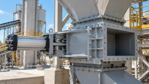
Selecting the right drive system determines whether a big size slide gate valve operates reliably or stalls under heavy head pressure. We engineer and calibrate four primary drive mechanisms depending on cycle frequency, stroke length, and the shear resistance required for your specific bulk media. Explore our broader line of valves and flow control equipment to see how these drive packages integrate across our heavy-duty product range.
Pneumatic Slide Gate Valve for Rapid Automated Cycling
For batching systems, emergency shutoffs, and high-frequency discharge points, pneumatic drives offer the fastest operation.
Cycle Speed: Full stroke in 3 to 10 seconds, depending on gate span.
Double-Acting Cylinders: Fitted with oversized bores, magnetic pistons, and integrated cushions to absorb shock at stroke termination.
Control Packages: Standard solenoid valves, flow controls for speed regulation, and non-contact proximity switches for open/closed confirmation.
Electric Multi-Turn Actuators for Precise Positioning and PLC Feedback
When handling continuous process streams, an electric slide gate valve big size configuration gives you variable positioning rather than basic on/off service.
Modulating Control: Compatible with 4–20 mA or digital fieldbus protocols (Modbus, Profibus) for automated flow throttling.
High-Torque Drive Units: Paired with precision ACME screw shafts or rack-and-pinion gearboxes to manage heavy drag loads.
Fail-Safe Integrity: Integrated torque limit switches stop motor drive immediately if a hard tramp metal obstruction enters the throat, preventing motor burnout and bent blades.
Hydraulic Drive Cylinders for Extreme Bulk Loads and Heavy Clinker
Deep silo bottoms, head loads exceeding 15 meters, and packed abrasive clinker require raw cutting force that air cannot supply.
High Thrust Capacity: Generates up to 150 kN of force to shear through standing columns of dense aggregates.
Proportional Valves: Deliver smooth, shock-free gate motion even under extreme mechanical drag.
Power Units: We supply modular, skid-mounted hydraulic power units (HPUs) with dual redundant pumps and accumulator backup.
Manual Handwheel and Chain Wheel Override for Emergency Isolation
For low-cycle hopper maintenance or emergency bypass zones, our manual drive options eliminate electrical and piping dependencies.
Mechanical Advantage: Low-friction bevel gearboxes enable single-operator actuation against heavy material heads.
Overhead Access: Extended chain wheels with safety guides allow ground-level actuation on elevated bin outlets.
Dual-Drive Compatibility: Manual declutchable handwheels can be integrated into pneumatic and electric assemblies for routine maintenance shutoff.
Drive System Comparison Guide
| Actuation Type | Cycle Speed | Thrust / Cutting Force | Flow Regulation | Ideal Service Condition |
|---|---|---|---|---|
| Pneumatic | Fast (3–10 sec) | Moderate to High | On / Off | High-frequency hopper gates, batch hoppers |
| Electric | Moderate (15–60 sec) | High | Modulating (0–100%) | Metered bin feeding, automated PLC loops |
| Hydraulic | Controlled (5–20 sec) | Extremely High | On / Off or Throttling | Clinker chutes, deep ore bins, slag discharge |
| Manual | Operator dependent | Moderate (Gear assisted) | Coarse Isolation | Cleanout ports, maintenance isolation |
Structural Components and Engineering Design
Rigid Carbon Steel and Stainless Steel Outer Frames
A reliable slide gate valve big size setup starts with a solid foundation. Deflection in the outer housing causes immediate blade misalignment and seal blowouts.
-
- Heavy-gauge structural plate: Outer bodies are fabricated from thick-wall carbon steel (A36 or Q235B) or heavy 304/316 stainless steel plate, reinforced with exterior gussets to resist line strain.
- Flange rigidity: Continuous welded perimeter flanges eliminate twisting under the weight of deep material columns in dry powder transfer and cement fly ash conveying systems.
- Stress-relieved fabrication: Large-span valve bodies undergo thermal or mechanical stress relief before final machining to ensure dimensional stability over years of operation.
| Component | Standard Carbon Steel Build | Severe-Service Stainless Build |
|---|---|---|
| Main Frame | Heavy structural A36 steel plate | 304 / 316 / 316L stainless steel |
| Blade Plate | Hardened AR400 or hard chrome plated | High-tensile 304/316 with beveled edge |
| Internal Rollers | High-carbon steel with grease ports | Sealed 400-series stainless bearings |
| Hardware | Grade 8 zinc-plated / galvanized | 304 / 316 stainless steel fasteners |
Precision-Machined Blade Guides and Hardened Rollers
Sliding a massive steel blade against thousands of pounds of resting head pressure requires low-friction guidance. Rather than using crude slide bars that scuff and gall, we incorporate heavy-duty mechanical tracking.
-
- Hardened guide rollers: Submerged internal or side-mounted cantilevered rollers feature sealed, self-lubricating bearings that keep the gate blade centered under extreme downward force.
- Machined lateral guides: Precision-milled UHMW-PE, bronze, or hardened steel side tracks prevent blade skew during asymmetrical material loading.
- Low friction factor: Rolling contact reduces friction by up to 70% compared to traditional slide rails, lowering the thrust required from your pneumatic or hydraulic cylinder.
Self-Cleaning Seal Pocket Design to Stop Material Packing
The primary failure point in conventional gate valves is material packing into the end-seal area, preventing complete closure. Our heavy-duty slide gate valve solves this with a purpose-built end-cavity design.
-
- Beveled knife edge: The leading edge of the slide gate plate is chamfered to slice through standing material columns, compacted powders, and granular particulates.
- Deflection cavities and scrapers: As the blade nears full closure, an angled strike bar and internal wiper wipe the blade face clean, forcing residual material down into the discharge stream instead of packing into the rear frame.
- Live-loaded packing gland: Compression packing along the perimeter utilizes adjustable Belleville spring washers to maintain constant sealing pressure against the moving blade, even through extreme thermal shifts.
Integrated Limit Switches and Position Sensors
Automated process control requires dependable real-time valve position feedback. Our industrial slide gate valve frames include protected sensor mounts to prevent false signals caused by vibration and ambient plant dust.
-
- Inductive proximity switches: Non-contact sensors detect target flags mounted directly to the moving gate carriage, confirming full-open and full-closed positions.
- Continuous linear position transmitters: When used for throttling feed rates in automated loadouts, 4–20 mA or digital positioners track real-time blade percentage across the full stroke.
- Heavy-duty protective enclosures: Switch packages are housed inside bolt-on steel enclosures (rated IP66/NEMA 4X or explosion-proof ATEX/IECEx) to prevent damage from external impact, washdowns, and fugitive dust.
Custom Sizes, Dimensions, and Flange Configurations
Standard catalog sizes rarely match large storage silos, rail loadout bins, or expander chutes. We build each big size slide gate valve to match your exact structural footprint, eliminating the need for expensive structural reworking in the field.
Square, Rectangular, and Round Opening Dimensions
Whether you are discharging dry powders through a round silo collar or controlling lump ore across a wide rectangular belt feeder, we tailor the clear opening to prevent material bridging.
Square Profiles: 24" x 24" up to 80" x 80" (600 mm to 2000+ mm) for symmetric hopper bottoms.
Rectangular Profiles: Custom aspect ratios up to 96" wide for wide discharge bins and chute gates.
Round Openings: Matched bores for standard process piping and vessel spouts, engineered with full perimeter sealing.
Custom Bolt-Hole Patterns and Matching Transition Chutes
To guarantee a bolt-up drop-in fit, we drill flanges to any standard or proprietary plant pattern:
Drilling Standards: ANSI/ASME B16.5, DIN, EN 1092-1, PN10/16, or bespoke legacy spacings.
Weld-Ready Flanges: Beveled or flat-faced flanges ready for direct duct or vessel attachment.
Integrated Transitions: Engineered inlet and outlet hoppers designed to mate oversized gates directly to downstream equipment or double flap valves for airtight airlock transfers.
| Parameter | Standard Build | Heavy Severe-Duty Build |
|---|---|---|
| Opening Range | 24" to 48" (600 mm to 1200 mm) | 48" to 96"+ (1200 mm to 2400+ mm) |
| Body Construction | Heavy welded structural carbon steel | Carbon steel frame with reinforced box trussing |
| Flange Patterns | ANSI 150#, PN10, or custom drillings | Custom layout per hopper footprint |
| Liner Options | Bare metal or UHMW | Bolt-in AR400, AR500, or ceramic tile liners |
Material Selections: Carbon Steel, Stainless, and AR400
A slide gate valve big size build must withstand both the static head pressure of the material bed and the wear from abrasive bulk motion. We select materials based on product chemistry and impact levels:
Structural Carbon Steel (A36/Q235B): Rugged, cost-effective baseline for non-corrosive aggregates, coal, and dry grain.
Stainless Steel (304 / 316 / 316L): Full stainless steel slide gate valve fabrication for chemical processing, fertilizer, food-grade applications, or outdoor corrosive washdown environments.
Abrasion-Resistant Liners (AR400 / AR500): Replaceable wear strips installed along the throat, deflector zones, and blade-contact rails to handle clinker, silica, bottom ash, and crushed rock.
High-Temperature Configurations for Calcined Materials and Hot Ash
Standard elastomer seals and close-tolerance guide clearances fail when handling high-temperature bulk solids. For calcined minerals, fly ash hoppers, and cement clinker lines operating above ambient conditions, we engineer:
Thermal Expansion Clearances: Precision-machined guide clearances prevent the sliding blade from binding as the metal expands under thermal cycling.
Extreme Heat Materials: 310-grade stainless steel frames, solid Stellite wear surfaces, or Hardox plates rated for service exceeding 900°F (480°C).
High-Temp Seals: Multi-layer braided graphite, fiberglass rope, and ceramic packing seals rated up to 1,600°F (870°C) with purge-air ports to preserve dust-tight shutoff.
Technical Specifications and Sizing Data
Standard Dimensions and Sizing Matrix
We configure both square and rectangular slide gate valve big size units to match standard flange patterns or custom hopper discharge footprints.
| Nominal Size (in / mm) | Opening Style | Standard Face-to-Face (mm) | Flange Pattern | Approx. Weight (kg) |
|---|---|---|---|---|
| 24" / 600 mm | Square / Round | 180 – 220 | ANSI 150# / DIN PN10 / Custom | 280 |
| 32" / 800 mm | Square / Rectangular | 200 – 260 | Custom Drilled / Slotted | 460 |
| 40" / 1000 mm | Square / Rectangular | 240 – 300 | Custom Hopper Pattern | 720 |
| 48" / 1200 mm | Square / Rectangular | 280 – 350 | Fabricated Heavy Flange | 1,150 |
| 60"+ / 1500 mm+ | Custom Engineered | Engineered to suit | Structural Girder Flange | 1,800+ |
Operating Pressure and Structural Load Limits
A heavy-duty bulk solids gate valve must withstand high vertical material loads without structural plate deflection:
-
- Design Pressure (Differential): Full atmospheric gravity discharge up to 1.5 bar (22 psi) standard; reinforced designs accommodate differential pressures up to 3 bar.
- Static Head Load: Engineered to handle standing material columns exceeding 30 meters of dense bulk solids without blade binding.
- Frame Rigidity: Maximum deflection under full static head is limited to less than $L/1000$ to maintain absolute seal contact and smooth blade transit.
Seal Temperature Ratings
We match perimeter seals, bonnet packings, and wear wipers to process temperatures and chemical exposure:
-
- Polyurethane / Nitrile (NBR): -30°C to +80°C (-22°F to +176°F); best for general ambient grains, sand, and fine aggregates.
- EPDM: -40°C to +120°C (-40°F to +248°F); suited for moisture-heavy and moderately corrosive environments.
- Viton (FKM): -20°C to +200°C (-4°F to +392°F); engineered for hot, mildly abrasive chemical and fly ash applications.
- PTFE / Graphite Impregnated: Up to +300°C (+572°F); self-lubricating, non-contaminating seal packs for hot process lines.
- Metallic / Hardened Inconel Wipers: Up to +500°C (+932°F); designed for calcined minerals, clinker chutes, and hot boiler ash.
Actuator Sizing Guidelines
Sizing an actuator for a large diameter slide gate valve goes beyond simple stroke speed. We calculate required drive force based on three key parameters:
-
- Frictional Shear Force: Calculated by multiplying the total bulk solid head load (weight of material resting on the closed blade) by the friction coefficient (μ) between the material and the blade surface.
- Packing and Seal Drag: The friction generated as the thick blade strokes through perimeter compression seals and stuffing boxes.
- Safety Margin Factor: A minimum safety factor of 1.3 to 1.5 is added to all pneumatic, hydraulic, and electric drive calculations to prevent stalls caused by lumps, tramp metal, or material caking.
Accurate thrust calculations prevent blade stalls when isolating deep silos discharging into downstream transfer points and telescopic loading spouts. We verify all head loads before finalizing cylinder bore diameters or gear ratios.
Big Size Slide Gate Valve vs. Alternative Industrial Valves
Selecting the right shutoff mechanism determines whether your bulk line runs cleanly or suffers from chronic blockages. While standard process valves handle liquids and gases, handling high-tonnage dry solids requires purpose-built engineering. Here is how a big size slide gate valve compares against other common discharge devices in heavy industrial setups.
| Feature / Valve Type | Big Size Slide Gate Valve | Industrial Knife Gate Valve | Heavy-Duty Butterfly Valve | Rotary Airlock Valve |
|---|---|---|---|---|
| Primary Material | Dry bulk powders, pellets, clinker, ores | Liquid slurries, pulp, wastewater | Clean liquids, light gases, fine dry powders | Dry granular materials and fine powders |
| Bore Opening | 100% full bore, zero flow obstruction | Full bore, narrow body pocket | Disc stays directly in flow stream | Compartmentalized rotor pockets |
| Material Bridging Risk | Extremely low | Moderate to high in dry solids | High (material catches on disc and stem) | Moderate (packing in rotor pockets) |
| Primary Function | Positive gravity shutoff and isolation | Pressure slurry isolation | Low-pressure throttling and shutoff | Continuous volumetric feeding / air sealing |
Slide Gate Valve vs. Knife Gate Valve for Dry Bulk vs. Liquid Slurries
An industrial knife gate valve is engineered primarily for liquid slurries, viscous fluids, and pulp where hydraulic pressure forces the blade against a seated seal. When used in dry bulk applications, knife gates regularly run into trouble:
Seat Pocket Jamming: Traditional knife gate seats have bottom pockets where dry materials pack tightly, preventing complete blade travel.
Guide Wedging: Fine powders force their way behind the blade bevel, causing the actuator to stall.
Our Solution: A heavy-duty slide gate valve big size configuration uses hardened perimeter roller tracks and self-cleaning blade edges that displace bulk powders across an open drop-through discharge, eliminating dead zones where material can wedge.
Slide Gate Valve vs. Butterfly Valve for Hopper Bottom Clearance
Many plant designers consider industrial butterfly valves due to their compact face-to-face dimensions and lower initial cost. However, beneath high-volume hoppers and storage silos, they present significant operational hurdles:
Flow Stream Obstruction: The butterfly disc sits permanently in the center of the discharge port. Coarse gravel, cement clinker, or damp grains accumulate directly on the disc face and shaft.
Bridging and ratholing: Material builds up around the disc edges, drastically choking discharge velocity and causing upstream bridging.
Seal Abrasion: Every time the disc turns through a moving head of abrasive material, the elastomer seat takes massive abrasive friction.
Slide Gate Advantage: A large diameter slide gate valve pulls completely out of the throat. When open, the bore is completely clear, giving gravity-fed solids an unobstructed path without wear on the blade.
Slide Gate Valve vs. Rotary Airlock for Isolation vs. Metered Feeding
We are often asked whether a facility needs an isolation gate or a rotary feeder. In high-capacity discharge streams, these units perform fundamentally different tasks, and they often work best paired together:
The Role of the Feeder: A heavy-duty rotary airlock provides continuous, metered volumetric transfer while holding a pressure differential between equipment (such as pneumatic conveying lines and dust collectors).
The Role of the Slide Gate: A rotary airlock cannot serve as a static isolation barrier for a full silo. If the airlock requires seal maintenance, bearing replacement, or clears a foreign metal obstruction, emptying the entire silo is impractical.
The Ideal Layout: Installing our bulk material handling valve directly above the airlock allows operators to isolate hundreds of tons of head load safely, letting maintenance crews service downstream feeders without draining storage vessels.
Industrial Applications for Large Diameter Gate Valves
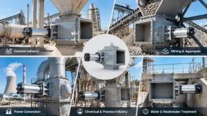
Cement Plants: Silo Bottoms, Bucket Elevators, and Clinker Chutes
Cement production demands absolute reliability under continuous material columns. We install our large-format gates at key discharge and transfer points throughout the plant:
-
- Silo Bottom Discharge: Positioned directly beneath storage and blending cement silos, our valves cut through dense columns of raw meal and finished cement without binding.
- Feed Chutes for Elevators: Installed at the inlet of heavy-duty bucket elevators, these gates meter and isolate material to avoid overloading the lift circuit.
- Clinker Handling: Fitted with hardened AR400 or hard-faced blades, our gates withstand the extreme abrasion and thermal stress of hot clinker chutes.
Mining and Minerals: Crushed Ore Bins, Screens, and Transfer Points
In mining and aggregate operations, large particle sizes quickly destroy standard valves. A heavy-duty slide gate valve big size configuration solves these failure points:
-
- Crushed Ore Surge Bins: Heavy-gauge carbon steel frames resist side-load deflection caused by uneven, high-impact rock loads.
- Vibrating Screen Inlets: Rapid shutoff capability allows immediate flow isolation during screen maintenance or material bypass cycles.
- Conveyor Transfer Chutes: Self-cleaning guide rails prevent wet fines and mineral slurry build-up from packing the seal track.
Coal and Power Generation: Bottom Ash, Pulverized Coal, and Fly Ash
Thermal power generation involves high temperatures, combustible dust, and fine, abrasive particles. We configure our large diameter slide gate valve systems to handle these specialized conditions:
-
- Bottom Ash Hoppers: Thermal expansion gaps and specialized packing withstand direct exposure to hot, quenching ash water and coarse slag.
- Fly Ash Silos and Precipitators: Dust-tight, pressurized perimeter seals prevent micro-fine ash leakage to maintain plant air quality standards.
- Pulverized Coal Chutes: NFPA-compliant, explosion-pressure-shock-resistant designs maintain structural containment in hazardous fuel-feeding zones.
Grain and Agriculture: Grain Elevators and Bulk Railcar Loading
Agricultural operations require high throughput without cross-contamination or grain damage. We provide smooth-bore, fast-cycling gates for massive transfer volumes:
-
- Terminal Elevators: Oversized square and rectangular gates accommodate discharge flows exceeding 2,000 metric tons per hour.
- Bulk Railcar and Vessel Load-Out: Integrated pneumatic or electric positioning controls allow automated, precise batch filling into rail hoppers and barge holds.
- Clean-Sweep Isolation: Polished stainless steel blades eliminate dead pockets, preventing mold growth, infestation, and product degradation.
Installation Best Practices for Oversized Slide Gate Valves
Installing a big size slide gate valve requires strict mechanical and structural discipline. Due to wide spans and heavy static loads beneath silos and bins, poor installation can twist the frame, bind the gate blade, and burn out actuators before the system even runs material. Based on field observations across our industrial projects, following core installation standards ensures long-term, jam-free operation.
Rigid Structural Framing to Prevent Valve Body Distortion
A slide gate valve big size model must never carry the unsupported weight of upstream bins or downstream chutes.
-
- Independent Support Systems: Anchor the valve body to dedicated structural steel beams rather than suspending it directly from connecting equipment flanges.
- Eliminate Torquing: Uneven foundation footings or warped support brackets twist the side guides. If the outer frame twists by even 1.5 mm across a large span, the blade will wedge and trigger actuator stalls.
- Expansion Joints: Always install flexible expansion joints below the valve outlet to isolate thermal growth and vibration from downstream conveyors.
Alignment Tolerances Between Hopper Flanges and Valve Openings
Mismatched transitions create internal shelves where bulk solids collect, pack, and eventually block the blade path.
-
- Centerline Matching: Align the hopper discharge flange and the gate bore to within a strict ±1.0 mm tolerance.
- Ledge-Free Chute Design: Ensure the inlet opening of the heavy-duty slide gate valve matches or slightly exceeds the upstream hopper flange ID. Never allow an upstream flange lip to protrude into the material drop zone.
- Flange Gasketing: Use full-face, high-durometer perimeter gaskets. Torque all flange bolts progressively in a crisscross pattern to prevent localized pinch points along the blade channels.
Pneumatic Air Line Sizing and Electrical Hookups
Oversized pneumatic gates require high instantaneous air volumes to maintain full opening and closing thrust.
-
- Dedicated Air Lines: Run minimum 1/2" to 3/4" ID rigid pneumatic lines directly to the cylinder ports. Restrictive 1/4" tubing starves the cylinder, leading to slow stroke speeds and erratic blade hesitation.
- Air Prep Stations: Mount a dedicated filter, regulator, and lubricator (FRL) unit alongside a local air surge tank within 2 meters of the valve cylinder.
- Clean Control Wiring: Wire limit switches and 4–20 mA position transmitters through shielded multi-conductor cables to prevent electromagnetic interference from nearby heavy drives and screen motors.
Pre-Commissioning Dry Stroke Testing and Seal Check
Before introducing bulk materials into the hopper, our engineering team requires a full mechanical verification sequence:
-
- Manual Clear Check: Inspect the internal body cavity, roller tracks, and seal pockets to confirm no weld slag or debris remains from construction.
- Low-Pressure Dry Cycling: Stroke the valve at 50% operating air pressure. The blade must travel smoothly through the entire cycle without stuttering, jumping, or scraping side plates.
- Seal Feeler Gauge Test: When fully closed, verify continuous contact between the blade face and the perimeter packing seals using a 0.5 mm feeler gauge to ensure complete dust-tight shutoff.
- Interlock Confirmation: Test open/close switch signals directly against the plant PLC to verify fail-safe shutoff sequences prior to loading head pressure.
Maintenance and Troubleshooting for Big Size Slide Gate Valves
Even a well-built big size slide gate valve requires structured preventive maintenance to ensure steady throughput and prevent unscheduled plant shutdowns. High-tonnage gravity streams, thermal cycling, and continuous abrasion eventually wear down contact surfaces. We focus on four core maintenance procedures to keep oversized gates operating reliably.
Clearing Packed Material in Guide Rails and Blade Slots
Fine powders, moist aggregates, and fly ash tend to migrate into perimeter channels:
Symptom: The blade binds or fails to achieve full stroke closure, tripping drive overloads.
Solution: Inspect the internal self-cleaning bevels and cleanout ports. Use compressed air lances to flush compacted fines from the side guides and downstream seal pockets. If your valve handles hygroscopic materials, install secondary purge ports to eliminate dead zones where moisture-cured crusts develop.
Adjusting and Replacing Worn Perimeter Packing Seals
Dust containment depends entirely on the integrity of the bonnet and perimeter packing:
Symptom: Visible dust plumes around the gate bonnet or hopper transition during discharge cycles.
Solution: Tighten the packing gland bolts evenly in half-turn increments to re-compress the gland packing against the blade. When the packing is fully compressed, slide in replacement braided PTFE, graphite, or silicone seals. For discharge gates installed beneath baghouse dust collectors, maintaining zero air infiltration is critical to prevent hopper condensation and clumping.
Troubleshooting Pneumatic Cylinder Stalls and Stroke Lag
Large-bore pneumatic actuators handle substantial shear loads, but they are vulnerable to supply-side issues:
Symptom: The pneumatic slide gate valve hesitates mid-stroke or crawls under a full standing head of material.
Solution: Check inline pressure gauges at the valve manifold during cycling. Large actuators require minimum sustained operating pressures of 80 to 90 PSI. Inspect solenoid exhaust ports for blockage, clear internal cylinder bypass leaks, and verify that the quick-exhaust valves dump air fast enough to provide full shearing force.
Checking Blade Wear and Structural Alignment Over Time
Severe service conditions erode the leading edges and throw structural frames out of square:
Symptom: Material blow-by across the closed blade edge or gouging along the side rollers.
Solution: Measure blade thickness at the impact center and inspect the shearing edge for scalloping or dishing. Use a straight edge to verify that heavy head pressure has not deflected the main frame. Replace worn hardened rollers, adjust side eccentric cam guides to re-center the gate, and swap out bolt-on AR400 wear plates before deep scoring reaches the primary stainless steel blade.
Custom Engineering and RFQ Checklist for Big Size Slide Gate Valves
Getting a quote for a custom big size slide gate valve requires precise process data to prevent deflection, jamming, and premature seal failure under deep material heads. Because oversized gates handle severe dynamic and static loads, our engineering team customizes every design around your specific layout and material properties. Integrating our gates seamlessly with your existing storage and discharge equipment ensures smooth bulk handling with zero transition choke points.
Key Parameters Needed for an Accurate Technical Quote
To size the blade thickness, frame reinforcement, and drive thrust accurately, we evaluate several baseline parameters upfront.
| Parameter | What We Need | Engineering Impact |
|---|---|---|
| Clear Opening Size | Square, rectangular, or round dimensions (e.g., 600 mm to 2500+ mm) | Sets frame structural load and overall footprint |
| Bulk Material Profile | Name, bulk density (kg/m³ or lb/ft³), particle size, moisture content | Dictates gate plate material, hardened liners, and deflection limits |
| Operating Head Load | Height of the material column resting directly on the closed blade | Determines actuator thrust requirements to shear through the standing column |
| Temperature Profile | Continuous and surge operating temperatures | Drives selection of perimeter packing, roller bearings, and expansion gaps |
| Mounting Orientation | Horizontal, vertical, or inclined chute angle | Affects guide roller placement and material deflection baffles |
Dimensional Drawings and System Layout Reviews
Before cutting steel, our engineering team verifies mating flange geometries against your structural drawings. For a heavy-duty slide gate valve, standard bolt circles often fail to align with custom hopper outlets.
-
- Flange Alignment: We match custom drill patterns, ANSI/DIN hole pitch, or slip-on transitions to prevent dead zones where dust accumulates.
- Overhead and Lateral Clearances: Large cylinder stroke lengths require adequate withdrawal room. We provide 3D step files to verify clearance around neighboring structural beams, ductwork, and maintenance access platforms.
- Flow Transitions: Rectangular-to-round or square-to-round transitions can be built directly into the valve body to save stack-up height.
Actuation, Control Voltage, and Fail-Safe Specifications
Operating a large size slide gate valve requires significant actuation power to break friction under head load. We tailor the drive mechanism to your facility's utility supply and safety logic:
-
- Drive Mechanism: Double-acting pneumatic cylinders, electric multi-turn drives, or heavy-duty hydraulic cylinders.
- Electrical Ratings: Control voltages (24VDC, 110VAC, 230/460VAC) and hazardous area ratings (explosion-proof, ATEX, or Class/Division ratings for dust-laden zones).
- Fail-Safe Logic: Fail-closed, fail-open, or fail-in-place configurations utilizing pneumatic air accumulator tanks or counterweights for emergency plant shutdowns.
- Feedback Systems: Proximity limit switches, mechanical end-of-stroke switches, or 4–20 mA continuous position transmitters for modulated gate positioning.
Quality Inspection Documentation and Material Test Reports
Every industrial valve shipped from our shop undergoes rigorous quality control to guarantee performance under demanding field conditions. Standard technical documentation packages include:
-
- Material Test Reports (MTRs): Full EN 10204 3.1 certification verifying chemical composition and mechanical properties for all carbon steel, 304/316 stainless steel, and AR-grade wear plates.
- Non-Destructive Testing (NDT): Dye-penetrant inspection on critical blade-to-shaft welds and load-bearing frame joints.
- Factory Acceptance Stroke Testing: Multi-cycle dry stroke tests checking limit switch responsiveness, seal integrity, and cylinder pressure draw before dispatch.
- Surface Coating Reports: Dry film thickness (DFT) certifications for industrial epoxy, high-temperature ceramic paints, or specialized shot-blast profiles.
Frequently Asked Questions About Big Size Slide Gate Valves
What opening size can be custom manufactured for a slide gate valve?
We fabricate custom slide gate valve big size units up to 2,500 mm × 2,500 mm (100 in × 100 in) in square, rectangular, and round configurations. For oversized silo outlets, non-standard transit chutes, or specific retrofit footprints, our engineering team tailors frame depths, bolt patterns, and flange geometry to match your existing flange connections directly.
Can a big size slide gate valve provide a 100% dust-tight shutoff?
Yes. Achieving a true dust-tight seal on a big size slide gate valve requires the right sealing configuration based on your bulk material:
-
- Adjustable Packing Glands: Braided PTFE, aramid, or graphite rope seals absorb blade deflection and prevent fugitive dust leakage to the atmosphere.
- Perimeter Seat Seals: Replaceable polyurethane, UHMW, or high-temp silicone seals maintain zero material bypass across the closed blade.
- Bonnet Enclosures: Fully enclosed housings isolate all internal moving parts and seals from ambient shop air and hazardous environments.
How do we prevent material from jamming the gate during closure?
Gate binding happens when bulk dry solids pack into the end guide slots during blade extension. We eliminate gate jamming using three core structural features:
| Anti-Jam Feature | Engineering Function | Ideal Bulk Material |
|---|---|---|
| Beveled Blade Edge | Shears through packed material beds and standing columns | Clinker, limestone, raw ore |
| End Relief Cavities | Gives displaced powder space to drop rather than wedge | Fly ash, cement, dry meal |
| Hardened Roller Guides | Replaces slide tracks to keep the blade centered under load | Heavy mineral aggregates |
What actuator type is best for large hopper discharge gates?
The right actuator depends on cycle speed, available utilities, and total load resistance:
-
- Pneumatic Cylinders: Best for rapid shutoff and standard silo discharge isolation above downstream equipment like belt conveyors. Dual-cylinder arrangements prevent blade binding on large gate spans.
- Electric Actuators: Ideal for precise, modulating material feed control via 4–20 mA PLC signals without the need for plant air lines.
- Hydraulic Power Units: Mandatory for extreme static head loads, high-density aggregates, or clinker chutes where shear force requirements exceed standard pneumatic cylinder ratings.
- Manual Bevel Gears: Practical for emergency maintenance isolation gates that cycle infrequently.
Can these valves handle abrasive dry bulk powders at high temperatures?
Yes. Our severe-service configurations handle material temperatures up to 800°C (1,470°F) and aggressively abrasive media. We line the valve body and clear opening with replaceable Hardox/AR400 wear plates or ceramic tiles. High-heat applications utilize 310/316 stainless steel blades, high-density pure graphite perimeter packings, and cooling stands that isolate pneumatic cylinders and electronics from thermal conduction.
What technical information do we need to provide for a quotation?
To deliver an accurate dimensional proposal and structural valve quote, provide these system parameters:
-
- Flange Opening Dimensions: Clear bore shape (square, round, or rectangular) and dimensions.
- Bulk Material Profile: Bulk density, particle size distribution, moisture content, and operating temperature.
- Material Head Pressure: Height of the material column directly resting on the closed gate blade.
- Actuation and Controls: Pneumatic, electric, hydraulic, or manual gear, along with preferred coil voltages and limit switch specs.
- MOC Requirements: Carbon steel, 304/316 stainless steel, or specific anti-wear liners.